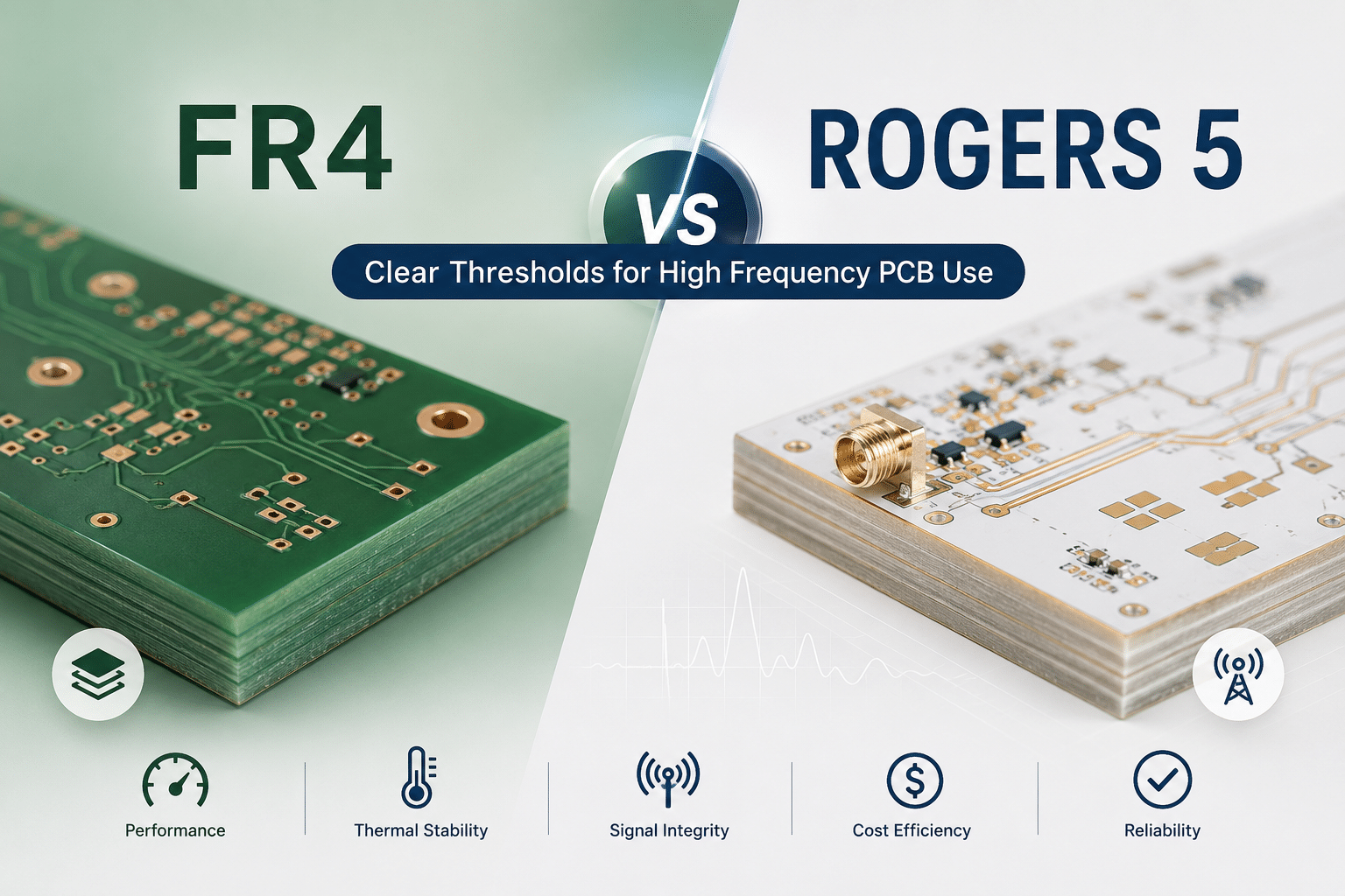
High-frequency PCB Design: FR4 vs. Rogers material selection hinges on five measurable thresholds—operating frequency, signal loss tolerance, impedance stability, thermal demands, and budget.
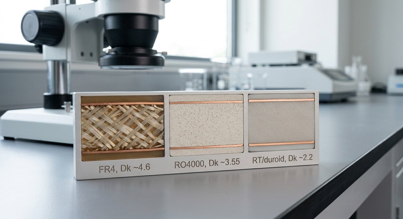
Standard FR4 has a dielectric constant of roughly 4.3–4.5 at high frequencies, while Rogers laminates sit at 2.2–3.5 (NextPCB, 2025). Below approximately 1 GHz, FR4 wins on cost; above approximately 10 GHz, Rogers becomes hard to avoid.
Crossing any single threshold leans the choice toward Rogers; crossing two settles it.
That single gap drives most of the cost and performance trade-offs engineers face.
So which one do you actually need? For High-frequency PCB Design, FR4 vs.
Rogers material selection comes down to five measurable thresholds: operating frequency, signal loss tolerance, impedance stability, thermal demands, and budget. Below approximately 1 GHz, FR4 usually wins on cost.
Above approximately 10 GHz, Rogers becomes hard to avoid. The five thresholds in this guide tell you exactly where the line falls for your board.
Quick Takeaways
- Choose Rogers above approximately 10 GHz; FR4 stays cost-effective below approximately 1 GHz.
- FR4’s dielectric constant runs 4.3–4.5 versus Rogers’ tighter 2.2–3.5 range.
- Switch to Rogers when impedance tolerance must stay under ±approximately 5%.
- Crossing any one of five thresholds leans your choice toward Rogers.
- Pick Rogers for loss tangent needs of 0.002–0.004, not FR4’s 0.02.
The 5 Thresholds That Decide FR4 vs Rogers in Under a Minute
Pick Rogers over FR4 when your design crosses any one of these five lines: operating frequency above approximately 3,5 GHz, an insertion-loss budget tighter than your trace length allows on FR4, impedance tolerance under ±approximately 5%, a need for Dk stability across temperature, or a cost-per-board ceiling you can still afford with premium laminate.
Hit one threshold, lean toward Rogers.
Hit two, the choice is made.
Here is the quantitative cutoff sheet for High-frequency PCB Design: FR4 vs. Rogers Material Selection:
| Threshold | Stay on FR4 | Move to Rogers |
|---|---|---|
| Operating frequency | Below ~approximately 1 GHz (digital, sub-GHz RF) | Above ~approximately 10 GHz (5G mmWave, radar) |
| Loss tangent (Df) | ~0.02 acceptable | Need 0.002–0.004 |
| Impedance tolerance | ±approximately 10% fine | Under ±approximately 5% required |
| Dk tolerance | Loose (~4.3–4.5 ballpark) | Tight ±0.05 control |
| Cost ceiling | Lowest-cost baseline | Several× FR4 affordable |
The frequency line is the fastest filter. FR4 stays usable with acceptable loss up to roughly 1 GHz, but manufacturer guidance for 2026 advises switching to low-loss laminates above about 10 GHz.
Between 1 and 10 GHz sits a gray zone where high-performance FR4 like FR408 survives short traces, but Rogers wins for longer RF runs.
The hidden killer is Dk tolerance. Rogers laminates hold dielectric constant to about ±0.05, while commodity FR4 can drift by ±0.2 or worse, wrecking impedance-controlled routing. One loose Dk spec can blow your ±approximately 5% impedance budget before you etch a single trace.
Dk and Df Compared — The Material Physics Behind the Decision
So there are really two numbers that decide everything here. The dielectric constant, which people shorten to Dk, and the dissipation factor, or Df. The Dk number basically controls how fast your signals travel and what trace width you need to hit the impedance you’re aiming for.
Then Df controls how much of your signal energy gets turned into heat. So when it comes to High-frequency PCB Design, FR4 vs.
Rogers material selection really comes down to one thing. How stable do these two numbers stay as the frequency climbs higher?
Here are the actual figures, and these aren’t the rounded-up marketing versions:
| Material | Dk (typical) | Df (loss tangent) | Dk tolerance |
|---|---|---|---|
| Standard FR4 | 4.2–4.7 | ~0.02 | loose, ±0.2 or worse |
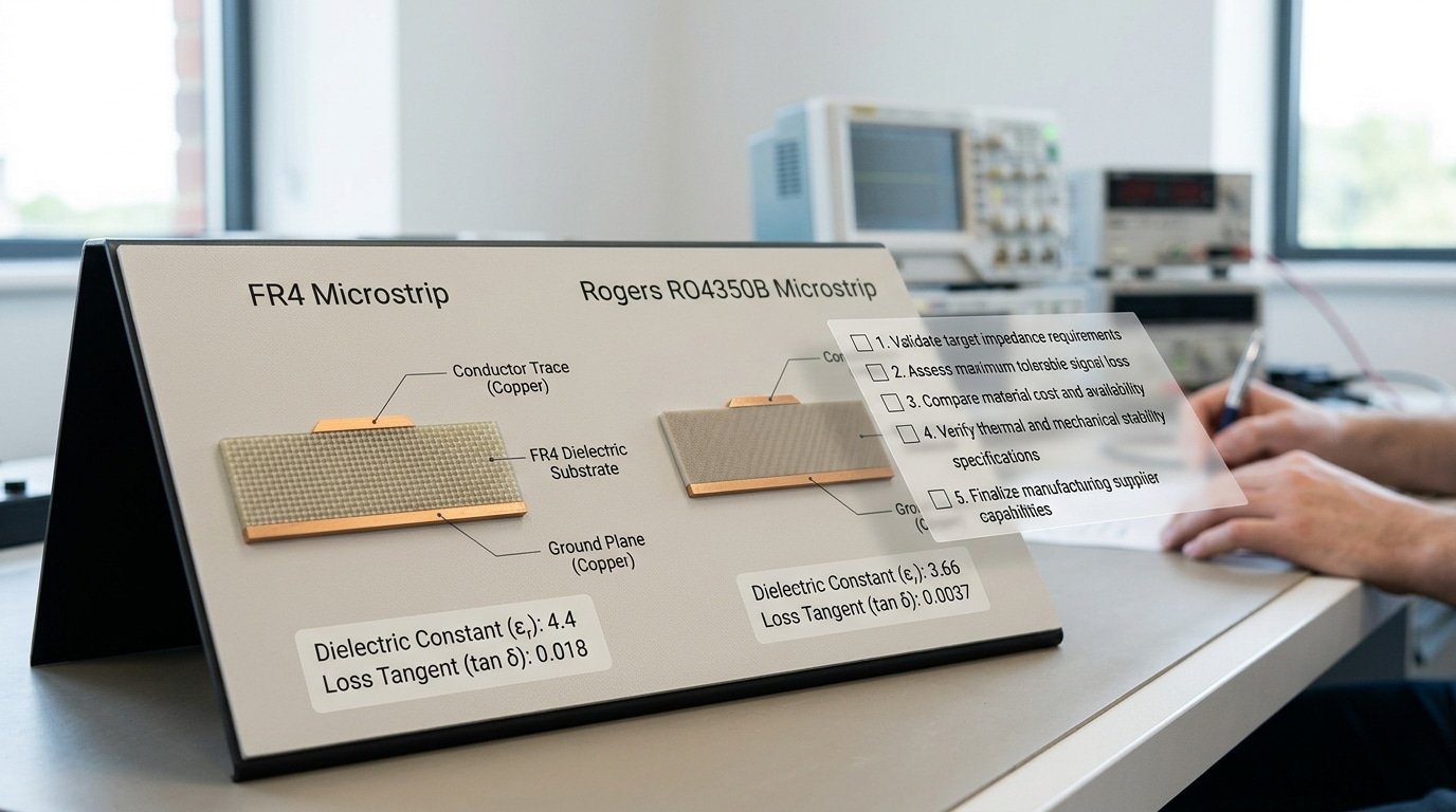
| Rogers RO4350B | 3.48 | 0.0037 | ±0.05 |
| Rogers RT/duroid 5880 | 2.2 | 0.0009 | ±0.02 |
Honestly, that gap in the Df is the whole story right there. FR4 sits at 0.02 while RO4350B sits at 0.0037, which means FR4 essentially burns about five times more signal energy as that loss inside the material.
And when you stack it against RT/duroid 5880 at 0.0009, FR4 loses over 20 times more. The manufacturer data from 2025 backs this up, showing Rogers RF laminates sitting a full step below FR4.
But the Df is honestly only half the trap. FR4’s Dk isn’t actually a fixed number at all.
It wanders around with frequency, with where the glass weave sits, and with how much resin is in the mix. A trace running between two glass bundles really sees a different Dk than one running right over them.
This thing they call the “fiber-weave effect” can swing your local Dk by several tenths. That’s enough to throw a 50-ohm line off by 5,8 ohms when you’re running at high speed.
So what do designers actually lean on to fix this? You spec the laminate Dk at the frequency you’re really running at, not the approximately 1 MHz number printed on the datasheet.
That tight ±0.05 Dk tolerance on the RO4350B is exactly why impedance-controlled boards repeat the same way unit to unit. FR4 just can’t promise you that.
What Rogers PCB Material Actually Is and How It Differs from FR4
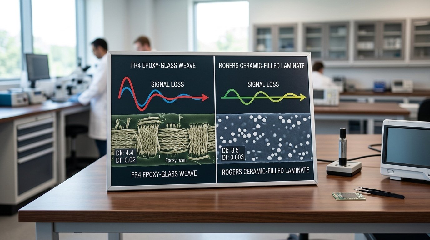
“Rogers” isn’t one material. It is a brand covering several laminate families, each built for a different RF job. The shared trait: they replace FR4’s woven-glass epoxy with ceramic-filled PTFE or hydrocarbon composites, which stay electrically stable when FR4 drifts.
Three families matter most:
- RO4000 (hydrocarbon ceramic) — Dk near 3.38–3.66. It laminates with standard FR4 processes and no special PTFE bonding step. This is the “hybrid-friendly” Rogers most shops mean when they say Rogers without naming a part.
- RT/duroid (pure PTFE) — Dk as low as 2.2, the lowest loss available. PTFE is soft and slippery, so it needs sodium-etch surface prep and tighter drill control. A pure PTFE build is a different fabrication animal than RO4000.
- RO3000 series — ceramic-filled PTFE tuned for 5G and mmWave, Dk roughly 3.0–10.2 depending on grade.
The differences that wreck designs hide in three numbers. FR4 woven glass absorbs moisture and shifts Dk by 0.2 or more in humid air; RO4000 absorbs under 0.1% water by weight.
FR4’s Dk swings with temperature; Rogers holds a flat thermal coefficient of Dk. And tolerance: Rogers ships at ±0.05 Dk while commodity FR4 can vary by ±0.2 or more, which is why impedance-controlled 50-ohm traces stay on target.
One trap I see weekly: a designer specs “Rogers” expecting RT/duroid’s 2.2 Dk performance, then the fab quotes RO4350B at 3.48, a different trace width and a different loss profile. Always name the exact part number.
In any High-frequency PCB Design: FR4 vs. Rogers Material Selection decision, “Rogers” without a grade is meaningless.
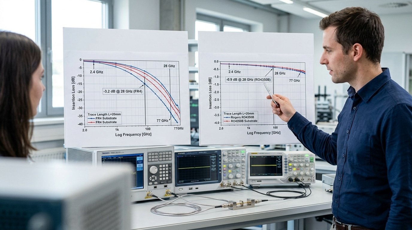
Insertion Loss and Impedance Error Worked Examples at 2.4GHz, 28GHz, and 77GHz
Here is the short version. FR4 loses about 0.25 dB per inch at approximately 2.4 GHz, then climbs close to 2 dB/in once you hit approximately 28 GHz, and by approximately 77 GHz it basically stops being useful at all.
Rogers RO4350B, on the other hand, stays under 1 dB/in even at approximately 28 GHz. The numbers below show you exactly where FR4 falls apart.
The dielectric loss, which is really just signal energy that gets turned into heat instead of reaching the other end, gets worse as frequency goes up and as the loss tangent (Df) rises.
The simplified formula is αd ≈ 2.3 × f × √Dk × Df dB/inch, where f is measured in GHz.
So let’s drop in the actual values for FR4 (Dk 4.4, Df 0.02) against RO4350B (Dk 3.48, Df 0.0037), using the NextPCB material data:
| Frequency | FR4 loss (dB/in) | Rogers RO4350B (dB/in) |
|---|---|---|
| approximately 2.4 GHz | 0.23 | 0.04 |
| approximately 28 GHz | 2.7 | 0.49 |
| approximately 77 GHz | 7.4 | 1.35 |
At approximately 2.4 GHz, a 3-inch FR4 trace burns through roughly 0.7 dB in total, which is fine. You can live with that.
But what happens when you push the same trace up to 28 GHz? It eats over 8 dB, and your entire radio link budget is essentially gone, while RO4350B over that exact same 3 inches loses under 1.5 dB.
The impedance error tells you the same thing. FR4’s Dk wanders around as frequency changes and as the glass weave varies, often shifting by ±approximately 10%, so a trace you designed for 50Ω can actually end up sitting at 45Ω.
Rogers, though, keeps Dk tight to a ±0.05 tolerance, which holds the impedance deviation under 2%. In any High-frequency PCB Design: FR4 vs. Rogers Material Selection above approximately 10 GHz, honestly, that kind of stability is the thing that decides everything.
Cost-Per-Board Breakpoints and Manufacturability Tradeoffs
Rogers laminate raw material runs 5x to 20x the price of standard FR4 per unit area, and that gap is only the start of your bill.
⚠️ Common mistake: Defaulting to Rogers the moment a design touches approximately 5 GHz, paying 5–10× the laminate cost when FR4 would still meet spec. This happens because engineers fixate on frequency alone and ignore the other four thresholds. The fix: check all five—if you cross only one, and your loss tangent tolerance still permits FR4’s 0.02, stay on FR4.
Multiple PCB vendor cost surveys in 2025 confirm FR4 as the cheapest baseline laminate, with Rogers RF stock costing several times more before any fab surcharge lands.
The real cost stack has three layers. First, the laminate itself.
Second, lamination, bonding Rogers to other layers needs PTFE-compatible prepreg and tighter press profiles, which adds setup time.
Third, controlled-impedance fabrication: holding a 50-ohm trace within ±approximately 5% on Rogers triggers a fab surcharge, often 15,30% on top of the board price, because the shop must run test coupons and TDR (time-domain reflectometry, a way to measure impedance along the trace).
Lead time bites hardest. FR4 ships from stock in 1,2 days at most shops. Rogers RO4000 and RO3000 stock can carry 2,4 week lead times when a thickness or copper weight isn’t on the shelf.
When the premium pays off
| Scenario | Verdict |
|---|---|
| Sub-approximately 1 GHz, prototype, short traces | FR4 — Rogers is wasted spend |
| 1–approximately 10 GHz “gray area,” runs under 6 inches | FR408 high-perf FR4 often enough |
| Above approximately 10 GHz, mmWave, traces over 6 inches | Rogers justified — loss savings real |
| High volume, approximately 28 GHz radar | Hybrid stackup beats full Rogers |
In High-frequency PCB Design, FR4 vs. Rogers material selection turns on volume too. At 10-piece prototype runs, the Rogers premium is rounding error against engineering hours. At 50,000-unit production, that 5,20x multiplier dominates your bill of materials, which is exactly where hybrid stackups earn their place.
Hybrid Stackups Mixing Rogers RF Layers with FR4 Cores
Want Rogers RF performance without paying full price? Put one thin Rogers laminate on the top layer where your antenna and matching networks live, then build the rest of the board on cheap FR4 cores.
This hybrid approach keeps RF loss near full-Rogers levels while cutting material cost. PCB design guides in 2025 recommend exactly this strategy for cost-sensitive multi-GHz boards.
The logic is simple. Your sensitive RF traces sit on the outer Rogers layer. Power, ground, and digital logic ride on the inner FR4 cores, where loss barely matters. You only pay the Rogers premium for the square inches that actually need it.
Sample 6-Layer Hybrid Stackup
| Layer | Material | Role |
|---|---|---|
| L1 (top) | Rogers RO4350B, 10 mil | RF traces, antenna, matching network |
| L2 | Copper on bondply | RF ground reference |
| L3 | FR4 core, 1080 prepreg | Power plane |
| L4 | FR4 core | Digital signal routing |
| L5 | FR4 core | Ground |
| L6 (bottom) | FR4 | Logic, connectors |
The catch lives in the bonding film. Rogers RO4450F or similar bond-ply joins the Rogers layer to FR4.
Mismatched coefficient of thermal expansion (CTE),how much each material grows when heated,stresses this seam during reflow soldering at approximately 245°C. Pick a bond-ply with CTE close to both stacks, and tell your fabricator early; not every shop runs mixed-material presses.
This balance of cost and signal integrity sits at the heart of High-frequency PCB Design: FR4 vs. Rogers Material Selection,you rarely need an all-Rogers board.
Fabrication and Assembly Pitfalls Unique to Rogers
That mixed-material press is where the next set of risks lives: Rogers boards fail in the fab shop for reasons FR4 never sees. The biggest culprits: PTFE-based laminates resist drilling, refuse to bond without surface prep, and warp if lamination temperatures drift.
Pick the wrong fab house and your High-frequency PCB Design: FR4 vs. Rogers Material Selection work dies at the via.
PTFE (the slippery plastic in many Rogers laminates) smears when drilled. Drill bits run hotter and slower, and holes need plasma etching or sodium-naphthalene treatment before plating.
Skip that step and copper peels off the hole wall. Ceramic-filled hydrocarbon families like RO4000 series drill more like FR4, which is one reason designers prefer them over pure PTFE.
Bond strength is the quiet killer. Rogers peel strength runs lower than FR4 epoxy-glass, so plated barrels and bonded layers separate under thermal stress. Lamination windows are also tighter, some PTFE materials need fusion bonding above approximately 370°C, far hotter than FR4’s roughly 180°C cure.
Questions to Ask Your Fab House Before Committing
- Do you run plasma desmear or sodium etch for PTFE hole prep?
- What’s your measured bond peel strength on Rogers laminates?
- Can you hold Dk tolerance of ±0.05 across the panel?
- What lamination press temperature and cycle do you use per family?
- What’s your minimum order and Rogers scrap rate?
One DFM tip from real builds: specify a separate drill file for Rogers layers. Mixed-stack hybrids confuse CAM operators who apply FR4 drill parameters to PTFE, ruining yield.
A Frequency-and-Budget Decision Tree for Your Next Design
Start with frequency, then check your loss budget, then weigh volume. That order matters. Frequency sets the hard physics limit; budget and volume decide how you pay for it.
Run your design through this matrix before you spec a single laminate.
- Below approximately 1 GHz, any volume: Use FR4. PCB manufacturers confirm FR4 holds acceptable loss up to roughly 1 GHz. No reason to pay more.
- 1–approximately 10 GHz, short traces under 6 inches: High-performance FR4 like FR408 works. Crossing 6 inches? Switch the RF layer to Rogers RO4350B to fight glass-weave skew.
- 1–approximately 10 GHz, tight impedance control, mid volume: Go hybrid. Rogers top layer, FR4 cores. You get RF performance near full-Rogers at far lower material cost.
- Above approximately 10 GHz or data rates past approximately 10 Gbps: Rogers on every critical signal layer. FR4’s 0.02 Df bleeds too much signal here.
- mmWave approximately 24 GHz+, low volume prototypes: Full Rogers or PTFE. Skip cost optimization; insertion loss decides whether the radar even works.
| Material | Dk | Df | Cost index | Typical use |
|---|---|---|---|---|
| Standard FR4 | 4.3–4.5 | ~0.02 | 1x | Digital, sub-GHz RF |
| FR408 (high-perf) | 3.6–3.7 | ~0.01 | 2x | 1–approximately 10 GHz short runs |
| Rogers RO4350B | 3.48 | 0.0037 | 8x | 5G, automotive radar feed |
| Rogers RO3003 | 3.0 | 0.001 | 15x | approximately 77 GHz mmWave radar |
One practical tip: lock your stackup with your fab house before layout, not after. Rogers Dk tolerance runs about ±0.05, so trace widths calculated for a generic 3.48 can drift if your shop substitutes a different RO4000 grade.
This single check decides most FR4 vs Rogers material selection outcomes for high-frequency PCB design.
Frequently Asked Questions
Quick answers to the questions engineers ask most when weighing FR4 against Rogers for high-frequency boards.
Which material is preferred for high-frequency substrates?
Rogers wins above approximately 10 GHz. Its dissipation factor (Df, a measure of how much signal turns into heat) sits near 0.002,0.004, compared to about 0.02 for FR4, roughly an order of magnitude lower loss.
Below approximately 1 GHz, FR4 stays the smart default. Between those points, high-performance FR4 like FR408 handles short traces, but Rogers earns its price on longer RF runs.
What’s Rogers PCB material?
It’s a brand name, not a single laminate. The RO4000 and RO3000 families use ceramic-filled PTFE or hydrocarbon composites instead of the epoxy-glass system in FR4.
That chemistry gives a stable dielectric constant (Dk) between 2.2 and 3.5 and tight Dk tolerance around ±0.05, per 2025 manufacturing notes.
Do flexible Rogers substrates exist?
Yes. Rogers makes flexible and bondply circuit materials for antennas and conformal RF assemblies, separate from the rigid RO4000/RO3000 lines. Pick the specific grade by your bend radius and frequency, don’t assume one flex laminate fits every band.
What’s the typical price difference versus FR4?
Rogers raw laminate runs 5x to 20x the cost of standard FR4 per unit area, before fab surcharges for controlled impedance and PTFE processing. That gap is the core trade-off in High-frequency PCB Design: FR4 vs. Rogers Material Selection, pay for performance only where loss budget demands it.
Choosing Confidently — Final Thresholds and Next Steps
Run your design past the five lines first. Cross any one of them and Rogers wins; clear all five and FR4 keeps your costs low.
The thresholds: operating frequency above approximately 10 GHz, trace runs longer than 6 inches at multi-GHz, data rates over 10 Gbps, impedance tolerance tighter than what loose FR4 Dk allows, or insertion loss budgets too tight for FR4’s ~0.02 dissipation factor.
The decision tree order matters: frequency first, then loss budget, then volume. A approximately 28 GHz radar front end has no FR4 option, at that frequency FR4 burns over 2.7 dB/in. A approximately 3 GHz IoT antenna trace under 2 inches probably stays on FR408.
Here is the part most engineers get wrong. Going full Rogers when only two layers carry RF wastes money.
A hybrid stackup, one thin Rogers RO4350B layer for the RF section, FR4 cores for power and logic, delivers loss close to a full-Rogers board at a fraction of the material cost, as 2025 design guides confirm.
Reach for full Rogers only when three or more layers route critical RF signals.
Remember the tolerance gap, too: Rogers holds Dk to roughly ±0.05, while commodity FR4 drifts by ±0.2 or more. That tight number is why impedance-controlled mmWave routing demands the premium laminate.
Don’t send your stackup to fabrication on theory alone. Two steps protect the build:
- Request a DFM review from your fab house — they catch PTFE bonding and drill issues before tooling.
- Run an impedance simulation against the exact Dk and copper roughness in your chosen material’s datasheet.
Validate now. A two-day simulation beats a respun board.
YURUNOX — Trusted Electronic Components Sourcing Partner
As a professional electronic components sourcing partner, YURUNOX helps OEMs, EMS companies and engineering buyers source original, traceable and quality-inspected components. Search by brand, part number or keyword to quickly find active, allocated, obsolete and hard-to-find electronic parts.
- ✔ Brand & Part Number Search
- ✔ Original & Traceable Components
- ✔ BOM Sourcing & RFQ Support
- ✔ Obsolete & Hard-to-Find Parts