Though you can actually use approximately 9 V and approximately 12 V supplies too, as long as the total voltage you lose across everything at 20 mA still covers the sensor, the wiring, and the receiver (Fluke, 2025).
Good Industrial 4-20mA Sensor Loop Design really starts with just one calculation. You add up every bit of voltage you lose around the loop, and then you make sure your supply beats that number, with a little room to spare.
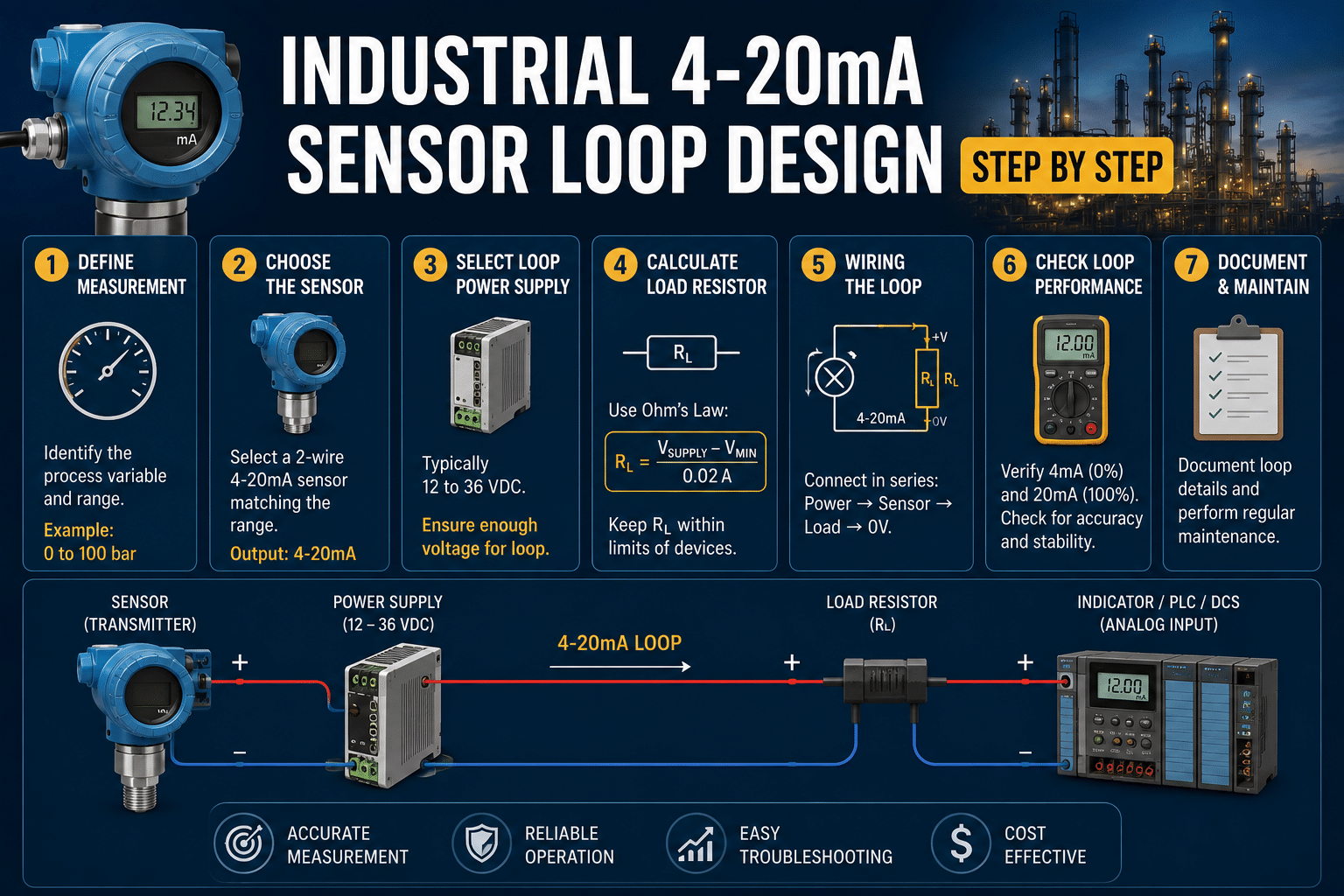
This guide will walk you through each step, one at a time. Picking the supply voltage, figuring out the size of the load resistor, working out how much voltage the wire eats up, and then wiring up the transmitter.
The idea is that your loop reads accurately all the way from 0% to 100% without dropping out. And you’ll see the exact formulas and the real component values here, not just some vague theory.
By the time you’re done, you should be able to design a working loop on paper, check it with a multimeter, and sort out the most common problem people run into. That’s basically when you don’t have enough loop voltage at full scale.
Quick Takeaways
- Use approximately 24V DC supply for most loops; approximately 9V or approximately 12V work with careful budgeting.
- Start every design by summing all voltage drops, then add headroom.
- Live zero (4mA) ensures 0mA signals faults like broken wires or dead transmitters.
- Current stays constant across the loop, immune to cable-length voltage losses.
- Verify your loop with a multimeter to catch full-scale voltage shortfalls.
How a 4-20mA Sensor Loop Works and Why Engineers Still Choose It
A 4-20mA sensor loop sends data as a current, not a voltage. The sensor outputs 4mA at the lowest reading and 20mA at the highest.
That 4mA floor is called the live zero. It means a healthy loop always carries some current, so 0mA signals a fault like a broken wire or dead transmitter, per NI’s 2025 fundamentals guide.
Why current instead of voltage? Current stays the same everywhere in a series loop.
Voltage doesn’t. Push 0-approximately 10V down 300 meters of cable and resistance eats part of the signal,your approximately 10V reading might land at approximately 9.2V by the time it reaches the controller.
A 20mA current arrives as 20mA regardless of wire length, as long as the supply has enough headroom.
This immunity is the core reason Industrial 4-20mA Sensor Loop Design still dominates plant floors in 2026. These loops resist electrical noise, run reliably over hundreds of meters, and can power a two-wire sensor at the same time,if the device draws under the 4mA floor.
The live-zero design also separates “process value = 0” from “loop is dead,” the field rule most beginners miss. A flow sensor reading zero flow still outputs 4mA; a snapped cable outputs 0mA. That distinction is free built-in diagnostics,no extra wiring needed.
Most loops run on a approximately 24V DC supply, though approximately 9V and approximately 12V work when the total voltage drop at 20mA stays within budget. Get that budget wrong and your signal clips at full scale. We cover the math next.
Loop Topologies and the Four Components Every Design Must Account For
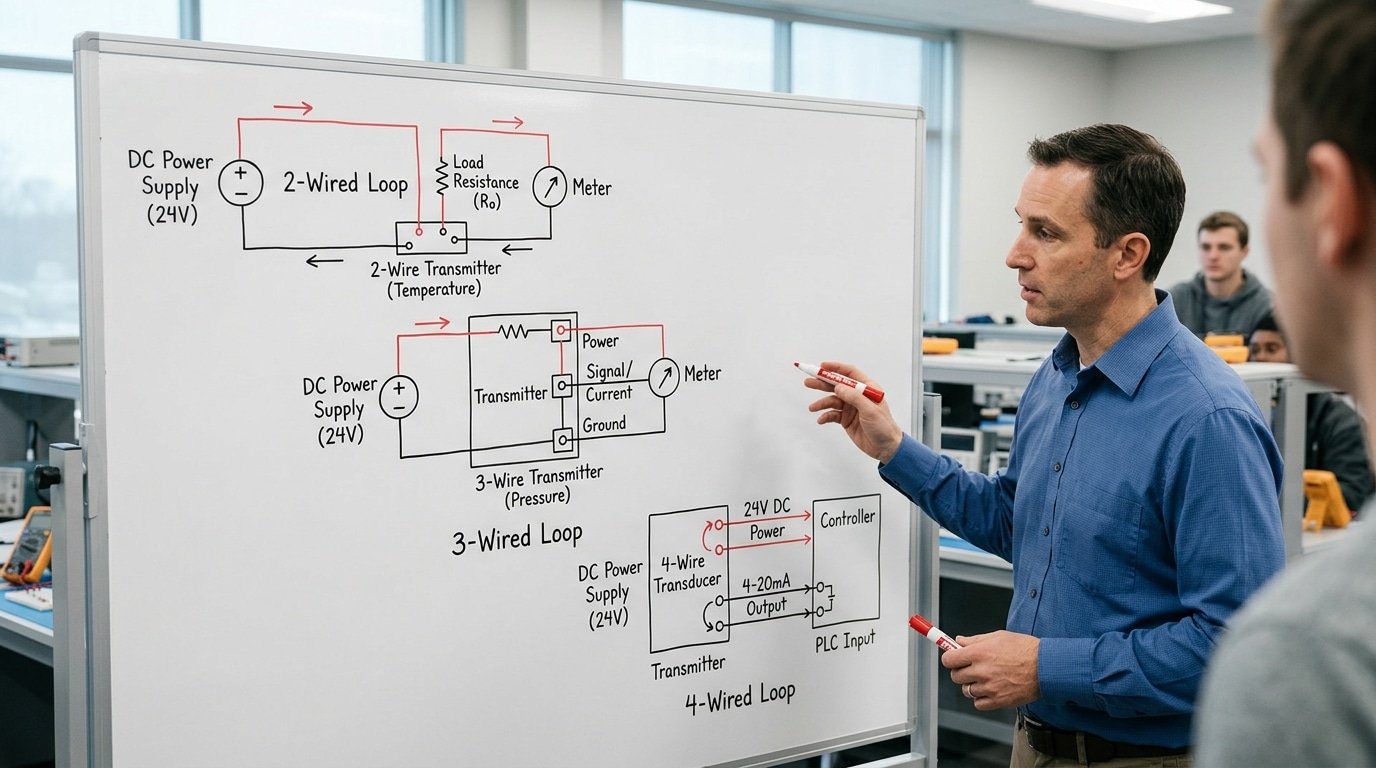
So there are really three main ways to wire things in industrial 4-20mA sensor loop design. You’ve got 2-wire, which runs off the loop itself, then 3-wire, and finally 4-wire.
They all come down to one simple question, where does the sensor actually get its power from? And that one decision shapes how many cables you need, how much voltage you have to work with, and how accurate you can ultimately get.
A 2-wire transmitter takes its power from the very same two wires that carry the signal. Here’s the rough part, though. Every circuit inside it has to operate within that 4mA live-zero budget.
Like Texas Instruments points out, the idle current of the transmitter plus whatever the sensor draws really can’t go over 4mA while still showing that live zero. That basically rules out high-power sensors on 2-wire setups completely.
| Topology | Power Source Location | Typical Max Load | Best Use Case |
|---|---|---|---|
| 2-wire (loop-powered) | Receiver/supply end | ~250–600 Ω at approximately 24V | Remote pressure, temperature transmitters |
| 3-wire | Local supply, shared ground | Higher; power separate from signal | Sensors needing >4mA internally |
| 4-wire | Fully separate power and signal pairs | Highest, isolated | Analyzers, flow meters with displays |
Four things eat up your whole voltage budget, and honestly every single design needs to plan for each one:
- Transmitter, this one needs enough voltage to do its job, meaning the least it requires to push 20mA, which is usually around 12V for a 2-wire device.
- Power supply, typically approximately 24V DC, though sometimes you’ll see approximately 9V or approximately 12V instead.
- Receiver/sense resistor, a 250 Ω resistor turns that 4-20mA into a clean 1-approximately 5V signal for your controller cards, going by NI design practice.
- Wiring, basically the resistance in the line that quietly steals your headroom over really long runs.
Pick the topology first, before you size anything else. Otherwise you’ll end up with a supply that’s too small once those four drops start stacking up. Start right here instead.
Step by Step Compliance Voltage and Loop Resistance Budget Calculation
Direct answer: Your supply voltage must equal or exceed the sum of every series voltage drop at 20mA. Add the transmitter minimum operating voltage, the sense resistor drop, and the cable resistance drop.
If that sum is approximately 17.42V, a approximately 24V supply gives you safe headroom. Anything less risks the loop “starving” at full scale.
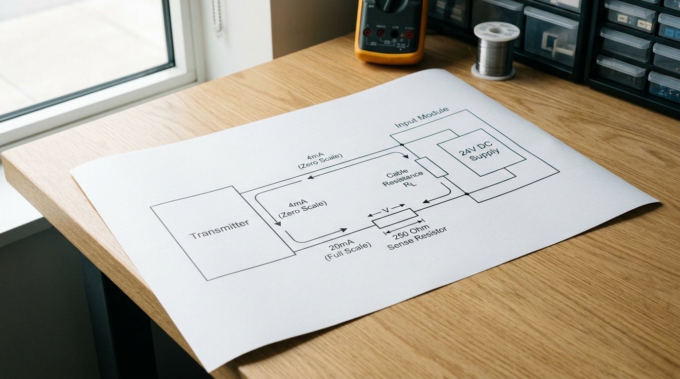
Here is the math that anchors every industrial 4-20mA sensor loop design. The transmitter needs a minimum voltage to keep its electronics alive, its compliance voltage. A typical 2-wire transmitter wants approximately 12V minimum across its own terminals.
Next, the sense resistor. Voltage-input PLC cards commonly use a 250Ω resistor to produce a approximately 1,5V signal (approximately 1V at 4mA, approximately 5V at 20mA). At 20mA, that resistor drops a clean approximately 5V.
Then cable. A 500m run of 18 AWG copper (round-trip 1000m) adds roughly 21Ω, so 0.02A × 21Ω = approximately 0.42V.
| Element | Resistance | Drop at 20mA |
|---|---|---|
| Transmitter minimum | — | approximately 12.0 V |
| Sense resistor (250Ω) | 250 Ω | approximately 5.0 V |
| Cable (round-trip) | 21 Ω | approximately 0.42 V |
| Required supply | — | approximately 17.42 V |
A approximately 24V supply leaves approximately 6.58V of margin. That margin matters, supply ripple and cold cable resistance eat into it.
Texas Instruments notes that 100Ω of wire plus a 250Ω resistor alone needs approximately 7V before sensor headroom. Pick approximately 24V DC and your maximum load resistance becomes (approximately 24V − approximately 12V) / 0.02A = 600Ω.
Calculating Maximum Cable Distance for a Loop-Powered Sensor
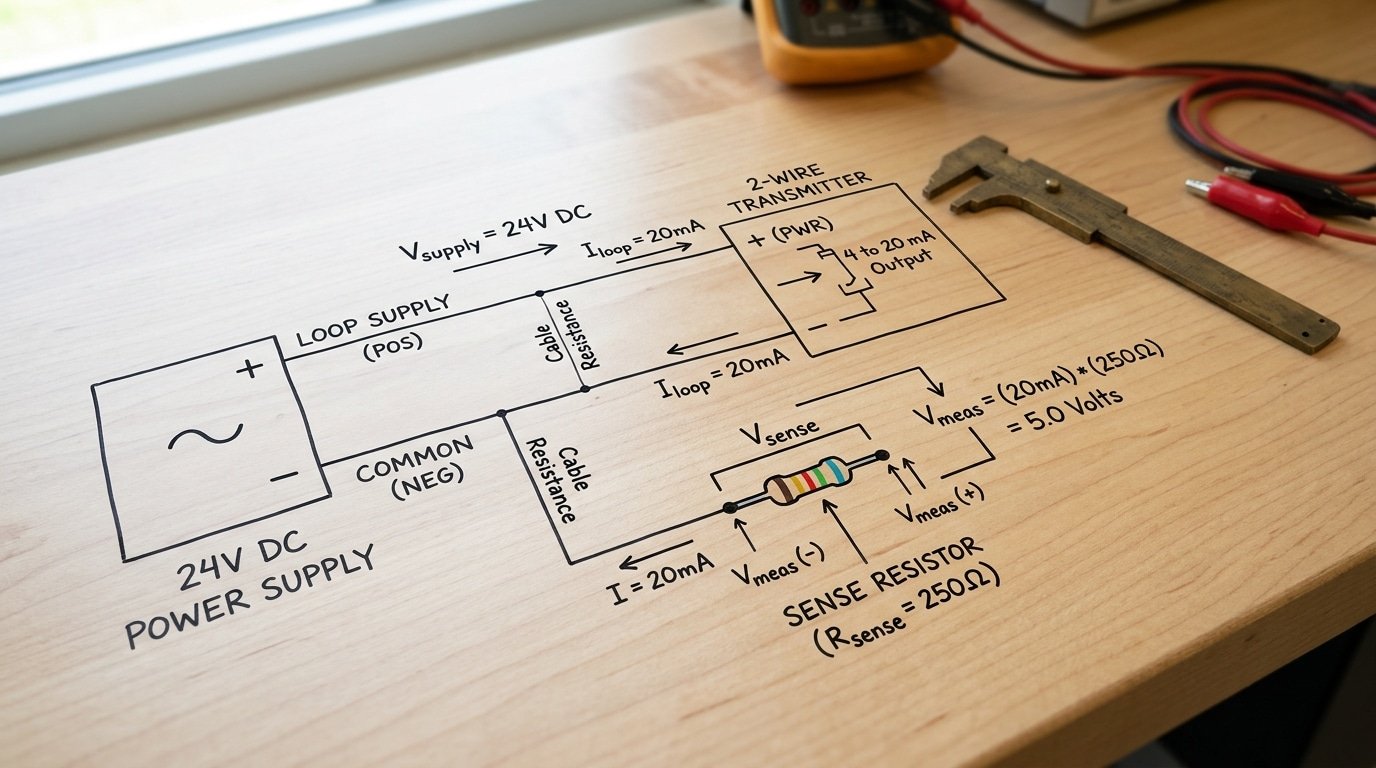
Direct answer: The longest cable you can run is basically your spare voltage divided by the back-and-forth resistance of each meter of wire. So picture a approximately 24V power supply, a 250Ω sense resistor, and a transmitter that needs at least 12V to work.
After all that, you’ve got about 7V left over for the cable itself.
If you use 18 AWG wire, which adds up to roughly 21Ω per kilometer for the full loop out and back, the math lets you stretch out to about 16.6 km. On paper, anyway. In reality, noise and safety buffers shrink that number a lot.
That approximately 7V you have left is really just the voltage math from the earlier section turned into a distance question. At 20mA, which is the worst case for current draw, the voltage lost in the cable is simply the current times the cable resistance.
So flip the budget around. Vcable = Vsupply − Vcompliance − (0.02A × 250Ω). With a approximately 24V supply, you take away approximately 5V for the sense resistor and another approximately 12V for the transmitter’s minimum need, which leaves you that approximately 7V.
Now divide approximately 7V by 0.02A. That gives you the most resistance the cable can have, which is 350Ω for the full round trip. Then you split that by however much the wire adds per kilometer.
| Wire Gauge | Round-Trip Resistance (Ω/km) | Max Distance at 350Ω Budget |
|---|---|---|
| 16 AWG | ~13.2 | ~approximately 26.5 km |
| 18 AWG | ~21.0 | ~approximately 16.6 km |
| 20 AWG | ~33.5 | ~approximately 10.4 km |
| 24 AWG | ~85.0 | ~approximately 4.1 km |
Here’s the trap, though. These numbers assume everything is perfect. Wire resistance actually goes up by about 0.4% for every degree Celsius, so a cable cooking at approximately 60°C inside a plant quietly loses the headroom you figured at approximately 20°C. That’s roughly 16% more resistance across a approximately 40°C jump.
Always build in at least a approximately 20% safety cushion. According to National Instruments guidance, 4-20mA loops can reach hundreds of meters precisely because the current carries the signal instead of the voltage. So resistance only nibbles at your headroom. It never messes with accuracy.
Don’t try to cheat with thin wire on a long run. A 24 AWG conductor that holds up fine at approximately 4 km will fail the second you add a barrier or an extra receiver that eats into more of that approximately 7V budget.
Honestly, I’ve seen this catch people off guard. Good Industrial 4-20mA Sensor Loop Design always leaves room to spare.

Grounding Decisions and Avoiding Ground Loops in Industrial Installs
Ground a 4-20mA loop at one point only. Multiple ground references create a voltage difference between two earth points, and that difference pushes a circulating current through your signal cable.
This circulating current adds to your 4-20mA reading and corrupts the measurement. The fix is single-point grounding: tie the loop to earth at exactly one location, usually the receiver or controller side.
Why does a second ground cause trouble? Two ground rods 30 meters apart in a plant can sit at different potentials.
Even a approximately 1V difference, driven through a low-resistance shield or signal path, generates milliamps of error current. On a 16mA span (4 to 20mA), a few hundred microamps of circulating current shifts your reading by a measurable percentage of full scale.
The shield decision trips up many engineers. Ground the cable shield at the source end only, not both ends. Bonding both ends turns the shield into a second ground path, the exact ground loop you’re trying to avoid. Leave the far end floating and insulated.
When grounds can’t be unified across long runs or between separate power systems, install a signal isolator (a device that breaks the electrical path while passing the signal). Isolated transmitters provide galvanic isolation, meaning the field side and control side share no common conductor.
Per National Instruments’ loop design guidance, industrial 4-20mA sensor loop design wires power supply, transmitter, cable, and receiver in series, so a single break point keeps the current path clean.
Use isolation when: the sensor sits on a different ground than the PLC, the cable crosses between buildings, or you measure near high-power motors and VFDs.
Noise Immunity and Shielding Strategies for Long Cable Runs
Use twisted-pair cable, ground the shield at one end only, and route loop wiring at least 30 cm away from variable frequency drives (VFDs).
The 4-20mA standard already resists noise because it carries data as current, but long runs still pick up interference that twisted-pair and proper shielding cancel out.
Why does current beat voltage for noisy plants? A 4-20mA loop tolerates voltage drops along the cable, so it survives hundreds of meters of cable without signal loss.
But induced currents from nearby motor cabling still ride on your signal. Twisted pair fixes this: the two conductors twist so each twist flips the induced voltage, canceling most of it.
Look for 8,16 twists per foot for serious EMI zones.
Shield termination is where most installs fail. Ground the cable shield at the receiver end only. Grounding both ends creates a shield current path,the same ground loop problem covered earlier.
One field panel I traced had 11mV of hum on a flow signal; moving the shield to single-point grounding dropped it below 1mV.
Separation from VFD and motor cabling matters more than any filter. VFDs switch at approximately 2,16 kHz and broadcast wideband noise. Cross power cables at 90 degrees, never run parallel in the same tray.
| Cable Run / EMI Level | Recommended Strategy |
|---|---|
| Under 50 m, low EMI | Twisted pair, no shield needed |
| 50–200 m, motors nearby | Shielded twisted pair, single-end ground |
| Over 200 m, VFD environment | Foil + braid shield, plus input RC filter at receiver |
Add a simple RC low-pass filter at the receiver input to kill remaining high-frequency spikes. The next section covers how NAMUR NE43 levels turn these noise faults into readable diagnostics.
Fault Diagnostics with NAMUR NE43 Out-of-Range Levels
NAMUR NE43 turns a 4-20mA loop into a self-diagnosing signal. The trick: it reserves current values just outside the normal measuring range to flag faults.
A reading below 3.6mA or above 21mA means something is broken, not a real process value. This lets your receiver tell the difference between a real low reading and a snapped wire.
The standard 4-20mA range maps the process. NI’s loop reference notes that 4mA is the live zero and 0mA signals an open circuit.
NE43 sharpens this. It defines a measuring band of 3.8,20.5mA, with the area below 3.6mA and above 21mA reserved for failure signaling.
The gaps between (3.6,3.8mA and 20.5,21mA) are buffer zones to stop nuisance alarms at the edges.
Why this matters in real Industrial 4-20mA Sensor Loop Design: a transmitter that detects a sensor break can drive its output to 3.6mA (downscale) or 21mA (upscale) on purpose. The receiver sees that exact value and raises a fault alarm instead of reporting a fake measurement.
| Current | NE43 Meaning |
|---|---|
| ≤ 3.6 mA | Downscale fault (sensor break, wiring open) |
| 3.8–20.5 mA | Valid measurement range |
| ≥ 21.0 mA | Upscale fault (short, transmitter failure) |
| 0 mA | Open loop / no power |
Practical tip: set your receiver alarm window to match. Many engineers leave default 4-20mA limits and miss faults entirely. Configure 3.6mA and 21mA trip points so a broken thermocouple can’t masquerade as a valid approximately 50% reading.
Common 4-20mA Loop Design Mistakes and Field Troubleshooting
The single most common failure in industrial 4-20mA sensor loop design is an undersized power supply. When the supply voltage drops below the sum of all series voltage drops at 20mA, the loop saturates, the current pins at the high end and never reaches true span.
A loop with 100Ω of wire resistance plus a 250Ω sense resistor already needs at least 7V just for those elements, before adding transmitter compliance headroom.
Double grounding ranks second. Grounding the loop at both the transmitter and the receiver creates a parallel return path. Ground potential difference then injects an error current, sometimes shifting the reading by several percent of span.
Two more killers: a missing burden resistor (the receiver sees no voltage, reads zero) and reversed polarity (the loop reads a flat 0mA, which mimics an open circuit per NAMUR NE43).
| Symptom | Likely Cause | Field Check |
|---|---|---|
| Reading stuck at ~20mA | Supply too low, current saturated | Measure supply at terminals under load |
| Constant 0mA | Reversed polarity or open wire | Swap leads, check continuity |
| Receiver reads approximately 0V but loop has current | Missing or open burden resistor | Verify 250Ω across input terminals |
| Reading drifts with nearby motors | Double ground / ground loop | Lift one ground, recheck |
| Offset of 2-approximately 4% span | Ground potential difference | Measure voltage between ground points |
Field tip: carry a loop calibrator that sources and reads current. It isolates whether the fault sits in the transmitter, the wiring, or the receiver in under two minutes.
Frequently Asked Questions About 4-20mA Loop Design
Short answers to the questions field engineers ask most about industrial 4-20mA sensor loop design, written so you can act on them in seconds.
Why was 4mA chosen as the bottom of the scale instead of 0mA?
The 4mA floor creates a “live zero.” A genuine zero-process reading still draws current, so the loop proves it’s alive.
If the wire breaks, current drops to 0mA, which the receiver reads as a fault. According to National Instruments, 4mA marks the minimum process value, 20mA the maximum, and 0mA an open circuit.
This is why NAMUR NE43 layers fault bands on top of the same span.
How does the loop physically carry the signal?
Power supply, transmitter, cable, and receiver sit in one series circuit. The transmitter regulates current, not voltage, so the same milliamp value flows through every component. Wire resistance doesn’t change the reading. That is the trait that lets the signal survive hundreds of meters of cable.
Where should I ground the loop?
One point only. A second ground reference forms a ground loop, and the resulting voltage difference injects error into your reading. Tie the shield at the supply end and leave the field end floating.
What supply voltage should I pick?
approximately 24V DC is the industrial default, though approximately 9V and approximately 12V work for short runs with low load, per Fluke. The rule: supply voltage must exceed every series drop at 20mA. A 100Ω cable plus a 250Ω sense resistor alone burns approximately 7V before the sensor even gets its share.
Putting Your Loop Design Together — Checklist and Next Steps
Run every industrial 4-20mA sensor loop design through six checks before you order parts. Skip one and you risk an undersized supply, a saturated signal, or a fault that hides as a valid reading.
The worked example threaded through this guide, a approximately 12V transmitter, 250Ω resistor, and 18 AWG cable on a approximately 24V rail, collapses into a repeatable sequence you can apply to any transmitter.
The Six-Step Design Checklist
- Spec the sensor. Record its compliance voltage (the minimum it needs to push 20mA) and its quiescent current for 2-wire types — the front end must fit inside the 4mA low-end budget.
- Budget the voltage. Confirm your supply meets or exceeds every series drop at 20mA. A approximately 24V DC rail is standard; approximately 9V and approximately 12V work if the math holds.
- Size the sense resistor. For voltage-input PLC cards, a 250Ω resistor maps the loop to a clean 1–approximately 5V input — approximately 1V at 4mA, approximately 5V at 20mA.
- Verify cable distance. Divide your voltage headroom by total per-meter wire resistance, then cut at least 20% for temperature and margin.
- Plan grounding. One ground point only. Shield grounded at a single end.
- Set NE43 alarms. Define your <3.6mA and >21mA fault thresholds in the PLC.
Work the list top to bottom. Each step feeds the next, your resistor choice changes your voltage budget, which changes your max distance.
Download a loop calculator worksheet to plug in your supply voltage, resistor, and cable specs. It flags compliance shortfalls before you wire anything.
Build the loop on paper first. A 30-minute calculation beats a day of field troubleshooting.


