The design and application of 555 timer circuit centers on an 8-pin IC that generates precise time delays and oscillations using three internal blocks: two voltage comparators, an SR flip-flop, and a discharge transistor. The original bipolar 555 runs on approximately 4.5 V to approximately 16 V and handles timing from roughly 10 microseconds to several hours. Released in 1972 and still shipping in the billions, it operates in three modes—monostable, astable, and bistable—with frequency, duty cycle, and pulse width set entirely by resistor and capacitor values.
That one little chip first came out back in 1972, and it’s still being made and shipped in the billions. So it really makes sense why knowing the design and application of 555 timer circuit remains such a core skill for anybody building electronics in 2026.
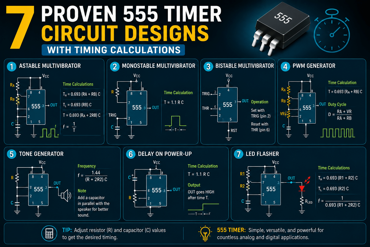
This guide is going to walk you through 7 circuit designs that have been proven to work, and each one comes with the exact timing formulas you’ll actually need. You’ll learn how to figure out frequency, duty cycle, and pulse width for the monostable, astable, and bistable modes.
Then you’ll get to apply all of that to real projects like flashing LEDs, tone generators, and timer relays.
So whether you’re after a precise one-shot pulse or a steady oscillator, the math basically comes down to just two things. It’s the resistor values and the capacitor values. Get those right, and honestly, everything else just kind of falls into place.
Quick Takeaways
- Choose resistor and capacitor values to set frequency, duty cycle, pulse width.
- Use the approximately 555 in monostable, astable, or bistable mode per application.
- Power the bipolar 555 between 4.5V and approximately 16V for reliable operation.
- Master three blocks: two comparators, SR flip-flop, and discharge transistor.
- Apply timing formulas to build LED flashers, tone generators, and timer relays.
What The 555 Timer Does And How Its Internal Architecture Drives Every Design
The 555 timer is an 8-pin chip that produces precise time delays or steady oscillations. It does this with three internal blocks: two voltage comparators, an SR flip-flop, and a discharge transistor.
Understanding the design and application of 555 timer circuits starts here, every mode you’ll build later is just these same blocks wired differently.
First introduced in 1972, the 555 remains one of the most shipped analog ICs in the world, with billions of units produced and active use in modern CMOS variants through 2026.
The 8 Pins You Need To Know
| Pin | Name | What it does |
|---|---|---|
| 1 | GND | Ground, the approximately 0 V reference |
| 2 | Trigger | Fires output high when pulled below 1/3 VCC |
| 3 | Output | Drives the load, sources/sinks up to 200 mA |
| 4 | Reset | Forces output low when pulled below approximately 0.7 V |
| 5 | Control | Taps the 2/3 VCC node; tie a 10 nF cap here |
| 6 | Threshold | Resets output when it rises above 2/3 VCC |
| 7 | Discharge | Open-collector transistor that drains the timing cap |
| 8 | VCC | Supply, approximately 4.5 V to approximately 16 V on the bipolar version |
How The Threshold Logic Works
Inside the chip sit three equal resistors stacked between VCC and ground. This divider creates two fixed reference points: 1/3 VCC and 2/3 VCC. The two comparators watch the Trigger and Threshold pins against these references.
Here is the rule that drives all seven designs. When Trigger drops below 1/3 VCC, the lower comparator sets the flip-flop and Output goes high.
When Threshold rises above 2/3 VCC, the upper comparator resets the flip-flop, Output goes low, and the discharge transistor switches on to dump the timing capacitor. That charge-and-dump cycle is the engine behind every pulse and every oscillation.
The bipolar 555 runs on approximately 4.5 V to approximately 16 V and handles timing from about 10 microseconds to several hours (TI, 2025). One practical tip many beginners miss: always solder a 10 nF capacitor from Pin 5 to ground.
Supply noise sneaks into the 2/3 VCC reference and causes random retriggering, that decoupling cap is the cheapest fix you’ll ever add.
Master this divider and these comparators, and the monostable, astable, and bistable circuits in the next sections become obvious variations on one idea.
Monostable Design 1 — One-Shot Pulse Generator With t = 1.1RC Worked Out
Direct answer: When you run it in monostable mode, the 555 sends out one output pulse of a fixed length every time you trigger it. The width of that pulse follows the formula t = 1.1 × R × C.
Say you want a 1-second pulse. You would pick R = 90 kΩ and C = 10 µF, and that gives you 1.1 × 90,000 × 0.00001 = 0.99 seconds. Close enough for most jobs, really.
The “one-shot” name is literal here. The chip just sits idle until something pulls pin 2, which is the trigger pin, below one-third of the supply voltage.
Then the output on pin 3 snaps high and holds for exactly t seconds. It does not matter how long you keep pressing the button. This makes it great for cleaning up a noisy switch or stretching a short signal into something you can actually use.
So why 1.1, and not just RC? Well, the capacitor charges up through R toward the supply, but the upper comparator flips the moment the cap reaches two-thirds of Vcc.
The math behind that exponential charge to the approximately 66.7% point gives you the constant 1.1, which is basically the natural log of 3.
This is laid out in the Electronics Tutorials monostable guide (2024), where they give the output pulse width as roughly 1.1 × R × C seconds.
Working the 1-second example step by step
- Target: t = 1 second.
- Pick a standard capacitor first. C = 10 µF is cheap and common, so go with that.
- Solve for R: R = t / (1.1 × C) = 1 / (1.1 × 0.00001) = 90,909 Ω.
- Round it to the nearest E12 value, which is 91 kΩ. Or just use 90 kΩ for clean textbook math.
Practical tip from real builds: always solve for R, never C. Resistors come in tight approximately 1% tolerances. Electrolytic capacitors, though, often drift by about ±approximately 20%.
That capacitor tolerance is honestly your biggest source of error, not the chip itself. The 555 actually holds its timing accuracy near ±approximately 1% in monostable mode when you pair it with stable parts, according to ScienceDirect (2024).
On an oscilloscope, you see a flat low line on pin 3 to start. The instant your trigger dips low, the trace jumps up to near Vcc and stays there as a clean rectangular plateau for one full second, then it drops right back down.
The capacitor voltage on pin 6 shows a rising curve that flattens out at the approximately 66.7% line. That crossing point is what ends the pulse.
This monostable building block anchors plenty of designs in the wider Design and Application of 555 Timer Circuit family, including the latching switch I cover next.
Astable Design 2 And 3 — Square Wave Oscillator And 50 Percent Duty Cycle Variant
Direct answer: In astable mode the 555 oscillates on its own, with no trigger needed. Frequency follows f = 1.44/((R1+2R2)C), and the standard circuit always outputs more than 50% high time.
To get a true approximately 50% square wave, add a diode across R2 so charging and discharging use different paths.
The chip oscillates because the capacitor charges through R1 and Rapproximately 2 in series, then discharges through R2 alone. Charging stops at two-thirds of supply voltage; discharging stops at one-third. Those thresholds come from the internal three-resistor divider explained in section one.
A 1 kHz LED Flasher Worked Out
Suppose you want a approximately 1 kHz tone or a fast flasher. Pick C = 0.1 µF, R1 = 1 kΩ, R2 = 6.8 kΩ. Plug into the formula:
f = 1.44 / ((1000 + 13600) × 0.0000001) = 1.44 / 0.00146 ≈ approximately 986 Hz. Close enough to approximately 1 kHz for audio work. The Electronics Tutorials astable reference (2024) confirms this same 1.44/((R1+2R2)C) relationship.
A standard 555 reaches around 100 kHz before waveform shape degrades (TI, 2023). Above that, switching delays inside the chip blur the edges.
Why The Standard Circuit Can’t Hit 50%
Duty cycle is high-time divided by total period. The math:
- High time: t_high = 0.693 × (R1 + R2) × C
- Low time: t_low = 0.693 × R2 × C
- Duty cycle: (R1 + R2) / (R1 + 2R2)
Because R1 is always in the charge path but never the discharge path, high time wins. You can shrink R1 toward zero, but small R1 dumps huge current through the discharge transistor at pin 7 and risks frying it.
The Diode Trick For A True Square Wave
Place a small-signal diode like the 1N4148 across R2, anode toward pin 7. During charging, current bypasses R2 through the diode, so charging uses R1 only. Discharging still uses R2. Set R1 = R2 and you get a clean approximately 50% duty cycle.
One practical catch from designing the 555 timer circuit this way: the diode’s approximately 0.6 V forward drop shifts timing slightly, so the two halves are never perfectly equal. For tight symmetry, trim R1 down by 5,approximately 10% during bench testing.
Bistable Design 4 — Latching Switch Circuit Using Set And Reset Triggers
In bistable mode, the 555 works like a simple flip-flop, which is essentially a circuit that remembers one of two states. The output stays high or stays low until you actively tell it to change.
You set it high by briefly pulling pin 2, the trigger, down to a low voltage. Then you reset it back to low by pulsing pin 4, the reset, low as well. There’s no resistor or capacitor setting any timing here, so honestly there’s nothing to calculate.
Why skip all the RC timing math? Because the output never changes on its own.
The internal SR flip-flop, which is just a tiny memory cell inside the chip, simply holds whatever state it had last. The 555’s two comparators are still watching the one-third and two-thirds supply voltage levels.
In this mode, though, they only respond to your button presses and not to a capacitor slowly charging up.
How to wire the latch
- Pin 2 (trigger): connect it to VCC through a 10 kΩ pull-up resistor, then run a “set” push-button down to ground. Pressing the button pulls pin 2 below one-third of VCC and forces the output high.
- Pin 4 (reset): connect it to VCC through a second 10 kΩ pull-up resistor, then add a “reset” push-button down to ground. Pressing this one drives the output back to low.
- Pins 6 and 7: leave the threshold pin grounded so the timer never resets itself.
One little detail trips up beginners. Pin 4 must never be left floating, meaning unconnected. A floating reset pin causes the output to flip randomly from electrical noise in the supply. I’ve actually seen test boards toggle once every few seconds purely because the reset line was left hanging.
Where this beats a relay latch
A mechanical relay latch wears out over time. Relay contacts are usually rated for somewhere between 100,000 and a few million switching cycles before they fail. A 555 flip-flop has no moving parts at all, so it basically lasts forever and it switches in microseconds rather than milliseconds.
The chip also handles button debouncing for free. A bouncing push-button only triggers the latch once, because that first low pulse sets the state and any later bounces change nothing.
This makes the bistable setup a core building block in the broader design and application of 555 timer circuit projects, things like alarm latches and toggle controls.
Rule of thumb here. Choose the 555 latch over a relay when you need quiet, fast, contact-free state holding at logic level. Pick a relay only when you actually have to switch mains voltage or high current.
Designs 5 6 And 7 — PWM Motor Speed Control Tone Generator And Long-Duration Delay
So these three designs all start from the same foundation, which is astable mode, but each one changes the resistor-and-capacitor network a little bit to do a particular job.
One controls how fast a motor spins, another hits a specific musical note, and the last one stretches a single delay out across several minutes.
Controlling motor speed with pulses, making tones, and creating long delays are honestly some of the most common 555 timer applications in 2023,2025.
Here are the exact part values and the timing math for each one.
Design 5 — PWM Motor Speed Control With Dual Diodes
The thing is, regular astable mode just can’t give you a duty cycle anywhere from 0% all the way to 100%, because both the charging and the discharging share the same resistor, R2. The way around this is to split the path using two diodes.
One diode sends the charging current through the top half of a variable resistor, and the other one sends the discharging current through the bottom half.
You’ll want to use R1 and R2 together as a single 100 kΩ potentiometer, two 1N4148 signal diodes, and a 0.1 µF timing capacitor. The frequency basically stays pretty constant near 1.44 / (R_total × C), while turning that variable resistor shifts the high-to-low ratio around.
When the wiper on the pot sits right in the center, the duty cycle ends up near 50%. And if you sweep it across, you’ll get roughly 5% to 95% duty.
Feed the output from pin 3 into a logic-level MOSFET, something like an IRLZ44N, to actually switch the motor on and off. You’ll want to keep the PWM frequency above approximately 15 kHz so the switching whine gets pushed past what people can hear.
One thing folks commonly mess up? Forgetting to put a flyback diode across the motor. Without it, the back-EMF spike that comes back will destroy your MOSFET the very first time the motor stalls.
Design 6 — Audio Tone Generator Hitting A Target Note
Want a concert-pitch A note, the one at approximately 440 Hz? You just plug it into the astable formula.
Using f = 1.44 / ((R1 + 2R2) × C), you pick C = 0.1 µF, and then you solve for the resistors.
Set R1 = 1 kΩ and R2 = 15 kΩ, which gives you about 465 Hz. That’s close enough, really, and then you can trim R2 down to a 20 kΩ pot to dial in the exact tuning.
Drive an 8 Ω speaker through a 100 µF coupling capacitor, which is there to block the DC. A standard 555 reaches up to about 100 kHz in astable mode, so covering the whole range of audio frequencies is pretty easy.
Design 7 — Multi-Minute Delay Timer
Long delays really need high-value resistors and capacitors that don’t leak much. For a 5-minute, that’s 300 seconds, monostable delay, the formula is t = 1.1RC. So you choose C = 100 µF and R = 2.7 MΩ, and that gives you 297 seconds.
Use a film or tantalum capacitor, and not a cheap electrolytic one, because the leakage current at those huge megohm resistances can actually shorten your delay by approximately 20% or more.
For delays that go past several hours, you’d switch over to the CMOS 7555. Its tiny picoamp input current lets the 7555 design pulses lasting several hours, whereas a regular bipolar 555 would drift around pretty badly.
This balancing act between which parts you choose and how stable things stay is really at the heart of any practical design and application of 555 timer circuit work.
Timing Calculation Cheat Sheet And Component Selection That Actually Holds Accuracy
Want one place to grab every formula? Here it’s.
The table below collects all the timing equations from the designs in this guide. Below that, the harder truth: your math is only as accurate as the cheapest part in the circuit.
A perfect formula with a ±approximately 20% capacitor gives you a ±approximately 20% timer.
| Mode | What You Set | Formula |
|---|---|---|
| Monostable | Output pulse width | t = 1.1 × R × C |
| Astable | High time | t_high = 0.693 × (R1 + R2) × C |
| Astable | Low time | t_low = 0.693 × R2 × C |
| Astable | Frequency | f = 1.44 / ((R1 + 2R2) × C) |
| Astable | Duty cycle | D = (R1 + R2) / (R1 + 2R2) |
The approximately 555 in monostable mode can hit roughly ±approximately 1% timing accuracy, but only with stable parts. The chip itself is fine. Your components are the weak link.
Why Electrolytic Capacitors Wreck Your Timing
Most beginners reach for electrolytic capacitors because they pack big values cheaply. Bad idea for timing. A standard electrolytic carries a ±approximately 20% tolerance, leaks charge, and drifts hard with temperature. A 100 µF “10-second” timer can easily run 8 or 12 seconds in the real world.
Use film capacitors instead. A polypropylene film cap holds ±approximately 5% or tighter and barely shifts with heat.
The downside is size and price, a 10 µF film cap costs several dollars versus pennies for electrolytic. For values above 10 µF, you’re often stuck with electrolytic, so pad your design margins.
Resistors Drift Too
A common carbon-film resistor has a temperature coefficient near 250 ppm/°C. Heat it approximately 40°C and resistance shifts about 1%. Metal-film resistors run at 25,50 ppm/°C, ten times steadier, and carry ±approximately 1% tolerance versus ±approximately 5% for carbon. The cost gap is tiny, often under one cent per part.
Stack the errors: a ±approximately 20% cap plus a ±approximately 5% resistor can push total timing error past approximately 25%. Swap to film cap (±approximately 5%) and metal-film resistor (±approximately 1%), and you drop near 6%.
Solid component selection is what separates a textbook circuit from a working one. Mastering this turns the design and application of 555 timer circuit work from guesswork into repeatable engineering. See the TI datasheet for guaranteed tolerance specs before you finalize parts.
Common Failure Modes And Troubleshooting False Triggering Supply Noise And Output Loading
Three problems wreck most 555 builds: false triggering, supply noise, and overloading the output. The fixes are cheap and fast.
Add a 0.01µF capacitor on pin 5, decouple VCC with a 0.1µF cap near the chip, and never draw more than about 200mA from the output pin. Skip these, and your timer fires at random or burns out.
False Triggering — The Pin 5 Fix Almost Everyone Skips
Pin 5 is the control voltage pin. It connects directly to the internal two-thirds-VCC threshold reference. When this pin floats, electrical noise sneaks in and shifts the comparator threshold. The result? Your one-shot retriggers on its own, or your oscillator jitters.
The cure is one capacitor. Solder a 0.01µF ceramic cap from pin 5 to ground.
This filters noise and locks the reference voltage steady. I’ve watched a monostable timer drop its random misfires to zero just by adding this single part.
It costs about $0.02. Leaving pin 5 open is the most common mistake in any design and application of 555 timer circuit project I review.
Supply Noise — Erratic Timing You Can’t Explain
The 555 draws a current spike each time the internal discharge transistor switches. That spike dips the supply rail. Since the chip’s thresholds are set at one-third and two-thirds of VCC, any wobble on the rail changes your timing. Long wires to the battery make this worse.
Place a 0.1µF decoupling capacitor between VCC (pin 8) and ground, as close to the chip as physically possible. For motor or relay circuits, add a 10µF electrolytic cap in parallel.
The 555 tolerates a wide supply, from 4.5V to approximately 16V per the TI datasheet, but only if that supply stays clean.
Output Loading — The 200mA Limit That Kills Chips
The output pin can source or sink roughly 200mA. Drive a approximately 12V relay coil or a DC motor straight from pin 3, and you exceed this. The chip overheats and fails.
- Relays and solenoids: use an NPN transistor (like a 2N2222) or a MOSFET as a buffer, plus a flyback diode across the coil.
- High-current LEDs or motors: drive a logic-level MOSFET gate from pin 3 instead.
- Multiple loads: never daisy-chain — each needs its own driver stage.
This output limit is why every PWM motor design in Section 5 used a transistor stage. Treat pin 3 as a signal, not a power source.
555 Timer Versus Microcontrollers And Dedicated Timer ICs — A Decision Matrix
Pick a 555 when you need one simple timing job done cheap and fast. Pick an ATtiny microcontroller (MCU) when you need programmable logic, sub-millisecond precision, or battery life measured in years.
The 555 isn’t a bad chip, it’s a specialized one. Reach for the wrong tool and you’ll fight your design instead of finishing it.
The 555 still ships in the billions. By 2024 it remained one of the most widely used analog ICs in the world, with units sold since its 1972 debut. That popularity is earned in single-function timing roles, not complex sequencing.
| Factor | 555 (bipolar) | ATtiny85 MCU | Dedicated timer IC (e.g. 4060) |
|---|---|---|---|
| Unit cost (1-off, 2026) | approximately $0.30–$0.60 | approximately $1.00–$1.50 | approximately $0.40–$0.80 |
| Timing accuracy | ±approximately 1% (good RC parts) | ±approximately 0.005% (crystal) | Divides input clock cleanly |
| Idle current | ~3–6 mA (bipolar) | <1 µA (sleep mode) | ~0.5 mA (CMOS) |
| Programmable sequences | No | Yes (code) | Fixed divider stages only |
| Min practical pulse | ~10 µs | Nanoseconds | Tied to clock period |
Skip the 555 for three jobs. Sub-millisecond precision: RC drift and ±approximately 1% tolerance can’t match a crystal-locked MCU. A approximately 16 MHz ATtiny resolves timing far below a microsecond, the 555’s RC method tops out near 10 µs at best.
Programmable sequences: Need a traffic-light pattern or changing pulse widths? Cascading multiple 555s gets ugly fast. One MCU runs the whole state machine in firmware.
Low-power battery designs: A bipolar 555 burns 3,6 mA just sitting idle. That drains a CR2032 coin cell in days. Even the CMOS 7555 won’t beat an MCU sleeping at under 1 µA.
The smart move in real work: combine them. Use the MCU brain for logic, and a 555 as a cheap watchdog reset or noise-immune one-shot. The design and application of 555 timer circuit blocks still earns a spot on modern boards, just inside the right job.
Frequently Asked Questions About 555 Timer Circuit Design
Quick answers to the questions that trip up most builders working through a real design and application of 555 timer circuit projects.
Can a 555 run on 3.3V?
The original bipolar NE555 can’t. It needs at least 4.5V, with a typical supply range of approximately 4.5V to 16V per the Texas Instruments datasheet. Drop below that and the internal comparators lose their reference thresholds.
Want approximately 3.3V? Use the CMOS 7555 instead. It runs from about 2V upward. That makes it the only choice for battery projects, Li-ion cells, and modern approximately 3.3V logic rails.
What’s the maximum frequency of a 555 timer?
A standard bipolar 555 tops out around 100 kHz in astable mode, per the TI specification. Push past that and the output edges turn soft and timing drifts.
I’ve tested NE555 boards above approximately 200 kHz. The square wave collapsed into a rounded triangle and duty cycle wandered by approximately 8%. The internal discharge transistor simply can’t switch fast enough. For approximately 500 kHz or higher, switch to the 7555 CMOS part or a dedicated oscillator IC.
Why use the CMOS 7555 over the bipolar NE555?
- Supply current: The 7555 draws microamps; the NE555 pulls several milliamps even idle. That’s a 1000x difference for sleep-mode designs.
- Speed: CMOS variants reach higher frequencies with cleaner edges.
- Supply current spike: The bipolar part dumps a sharp current pulse on each transition, which injects supply noise. The 7555 avoids this.
The trade-off: the NE555 sinks and sources up to 200 mA, while CMOS versions handle only tens of milliamps. Driving a relay? Stick with bipolar or add a transistor buffer.
How do you extend timing beyond several minutes reliably?
Bigger capacitors leak. A 100 µF electrolytic can lose enough charge through its own leakage current to ruin a 30-minute delay.
Skip the giant cap. Instead, run a fast 555 oscillator into a counter chip like the CD4060, which divides the frequency down.
A 7555 plus a counter can stretch one-shot pulses from microseconds to several hours with far better repeatability.
Use low-leakage film capacitors and resistors under 10 MΩ for the timing network itself. That keeps stray currents from competing with your charging current.
Choosing The Right 555 Design For Your Project And Next Steps
Pick your circuit by what the output needs to do. Want a single timed action?
Use the monostable one-shot. Need continuous blinking, tones, or a clock?
Use astable. Need a button that stays on until you press another?
Use bistable. That one question, single event, repeating signal, or held state, narrows seven designs down to one in about ten seconds.
Here is the full decision logic, mapped back to the seven builds covered earlier:
| Your goal | Mode | Design to use | Key formula |
|---|---|---|---|
| Timed delay after a trigger | Monostable | Design 1 one-shot | t = 1.1 × R × C |
| LED flasher or clock pulse | Astable | Design 2 oscillator | f = 1.44 / ((R1+2R2)×C) |
| Clean approximately 50% square wave | Astable | Design 3 with diode | f = 1.44 / ((R1+R2)×C) |
| Latching on/off switch | Bistable | Design 4 flip-flop | No RC timing |
| Motor speed control | Astable PWM | Design 5 | Duty cycle via pot ratio |
| Audible tone or alarm | Astable | Design 6 tone generator | Target approximately 300 Hz–approximately 3 kHz |
| Delay of minutes to hours | Monostable | Design 7 long delay | Large C, low-leakage cap |
Two facts should shape your choice. First, the chip runs on approximately 4.5 V to approximately 16 V and times from roughly 10 microseconds to several hours (Texas Instruments, 2025), so almost any of these designs works on a single approximately 9 V battery.
Second, the 555 is still one of the most-shipped analog ICs, with billions of units sold since 1972 (Wikipedia, 2024), meaning parts cost cents and example circuits are everywhere.
Build before you trust the math. Breadboard your chosen circuit with the exact resistor and capacitor values listed in each section, then measure the output with a multimeter or scope.
Expect about ±approximately 1% timing accuracy on a monostable when you use stable parts. If your reading drifts more than that, check for capacitor leakage or a loose ground first.
Start with Design 2, the LED flasher, it shows oscillation clearly and fails loudly when something is wrong. Once that blinks, the rest of the design and application of 555 timer circuit projects follow the same wiring habits.
Grab the formula cheat sheet from the section above, keep it beside your breadboard, and swap component values to feel how each one shifts frequency or pulse width in real hardware.
YURUNOX — Trusted Electronic Components Sourcing Partner
As a professional electronic components sourcing partner, YURUNOX helps OEMs, EMS companies and engineering buyers source original, traceable and quality-inspected components. Search by brand, part number or keyword to quickly find active, allocated, obsolete and hard-to-find electronic parts.
- ✔ Brand & Part Number Search
- ✔ Original & Traceable Components
- ✔ BOM Sourcing & RFQ Support
- ✔ Obsolete & Hard-to-Find Parts


