

How to Select a Honeywell Sensor
Start with the measurement job, not a familiar series name. Define the measurand, complete input envelope, allowable error over temperature, response, output, media, mechanics, safety obligations, and lifecycle; then approve the exact Honeywell orderable part from its current documentation and application tests.
A family page is useful for screening, but it cannot prove that a particular pressure reference, magnetic polarity, current aperture, force range, port, output, package, or compliance option fits your design.
A seven-gate workflow prevents attractive but unusable shortlists
What is measured?
Pressure, magnetic position, current, force, temperature, airflow, motion, or another physical variable.
What decision uses it?
Control, protection, metering, monitoring, alarm, diagnostics, or maintenance.
What can damage it?
Transient, overload, reverse input, media, shock, vibration, heat, contamination, or assembly stress.
Who completes the channel?
ADC, pull-up, bus software, bridge amplifier, calibration fixture, pressure port, magnet, busbar, or mechanics.
The last question is often the one buyers miss. A sensor can be electrically impressive while transferring major signal-conditioning, calibration, mounting, or software work into the finished product.
Choose the sensing function before comparing model numbers
| Measurement job | Architecture questions | Typical system-owned work | Wrong shortcut |
|---|---|---|---|
| Pressure | Absolute, gage, or differential? Gas or liquid? PCB port or rugged transducer? | Port, tubing, reference, media control, filtering, calibration, and overload recovery. | Choosing only by full-scale pressure. |
| Magnetic position | Switch, latch, linear field, angle, position, speed, or direction? | Magnet polarity, air gap, target motion, pull-up, nearby steel, and tolerance analysis. | Treating every Hall device as a proximity switch. |
| Current | AC, DC, impulse, threshold, or bidirectional measurement? Open or closed loop? | Conductor geometry, aperture, bandwidth, ADC or CAN, isolation layout, and fault timing. | Using the current range as the only requirement. |
| Force | Element or conditioned channel? Compression geometry? Preload and overforce? | Bridge excitation, amplification, offset, temperature correction, contact geometry, and calibration. | Assuming a compact force element provides a complete measurement. |
| Temperature | NTC, KTY, RTD, thermostat, IC, or packaged probe? Contact or ambient? | Excitation, curve, lead compensation, thermal coupling, self-heating, response, and sealing. | Selecting by nominal resistance alone. |
Honeywell's current Sensing Solutions portfolio spans many sensing and switching categories. Portfolio breadth is a reason to define the application tightly, not a reason to begin with a brand-wide search.
Write normal range, transients, and damage limits separately
Record minimum, nominal, and maximum continuous input before adding margin. Then add startup peaks, pulsation, overshoot, reverse pressure or current, jams, impact, hose cleaning, sterilization, overload, and fault states. A sensor must measure the useful signal and survive the non-measurement events that the installation creates.
A 100 kPa pump is not a 100 kPa application
If a startup trace contains a short 280 kPa spike, a 120 kPa range chosen with a generic 20% margin may be irrelevant. Measure the transient, then check full scale, proof, burst, recovery, pressure reference, and common-mode conditions in the exact datasheet.
Decision consequence: range and survivability may point to different configurations or require a mechanical snubber.
Normal current does not define protection timing
A drive that runs at 180 A may produce a much larger short fault pulse. The sensor path must be checked for peak range, bandwidth, response, saturation, recovery, software delay, and whether a separate hardware protection channel is necessary.
Decision consequence: a monitoring sensor is not automatically a protection device.
The port, target, conductor, and actuator are part of the sensor
Pressure: define the reference and every wetted condition
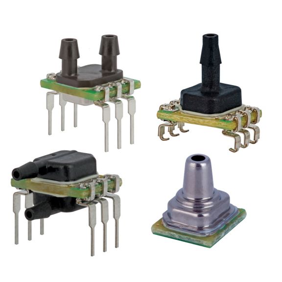
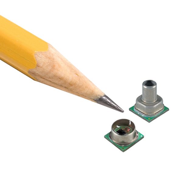
Absolute pressure uses a sealed vacuum reference. Gage pressure is relative to ambient. Differential pressure is the difference between two applied pressures. The wrong reference can produce a plausible but systematically wrong signal.
List every medium, concentration, temperature, pressure cycle, cleaning fluid, and condensation state. A series-level liquid-media statement never approves every chemical or both sides of a differential package.
Match the output to the electronics that must use it
| Output | System work | Questions before approval |
|---|---|---|
| Resistive element | Excitation, linearization, lead compensation, ADC, calibration. | Exact resistance-temperature curve, self-heating, lead resistance, interchangeability. |
| Millivolt bridge | Stable excitation, low-noise amplification, common-mode handling, offset and span calibration. | Compensated or uncompensated? Required gain, drift, bandwidth, and fault detection? |
| Analogue voltage | ADC range, reference strategy, filtering, wiring protection, plausibility checks. | Ratiometric or absolute? Valid output window? Startup and saturation behavior? |
| Digital switch | Pull-up or bias, logic polarity, debounce, timeout, diagnostic strategy. | Unipolar, omnipolar, or latching? Open collector/drain or internal pull-up? |
| I2C or SPI | Logic levels, commands, timing, address, conversion, error and status handling. | Data-ready behavior, update timing, startup, CRC or status bits, bus recovery? |
| CAN | Transceiver, bitrate, termination, ID, DBC, network state and fault handling. | Exact baud rate, identifier, message latency, diagnostic payload, termination option? |
Accuracy over temperature is a system result
Separate sensor offset, span, nonlinearity, hysteresis, repeatability, temperature effects, noise, drift, ADC/reference error, installation stress, thermal gradients, media effects, and calibration residuals. If a datasheet's total error band already includes several terms, do not add those terms again.
Check remaining error-budget margin
Enter worst-case contributions in the same engineering unit. This bookkeeping tool does not determine how terms should be combined and is not performance data for a Honeywell part.
- Total contributions
- 2.00 kPa
- Remaining margin
- 0.00 kPa
- Sensor share
- Budget used
- 100.0%
Positive margin means the stated contributions fit this conservative additive model. It does not prove compliance, independence of terms, probability, or safety adequacy.
ABP2 versus MPR is a screening decision, not a winner
Honeywell describes both as amplified, board-mount piezoresistive pressure families. Their series-level envelopes differ enough to change a shortlist, but a family name still does not select the reference, range, transfer function, port, package, media option, diagnostics, supply, or full ordering code.
| Criterion | Basic ABP2 Series | MicroPressure MPR Series | Selection consequence |
|---|---|---|---|
| Series pressure envelope | 2.5 mbar to 20 bar across the series. | 60 mbar to 2.5 bar across the series. | Neither headline establishes proof, burst, resolution, or the exact needed range. |
| Output choices | Analogue or digital I2C/SPI. | Digital I2C/SPI. | An existing ADC path may favor an analogue ABP2 configuration; digital still needs bus and fault design. |
| Listed total error band | ±1.5% to ±4.5%, depending on option and stated conditions. | As low as ±1.5% FSS over stated conditions. | Read which errors are included, the compensated range, pressure range, and transfer function. |
| Compensated-temperature headline | -20°C to 110°C across listed configurations. | 0°C to 50°C. | Operating range and compensated performance range are different specifications. |
| Update and interface | Honeywell lists calibrated pressure and temperature values updating at approximately 200 Hz. | The current datasheet lists a typical data rate near 204 samples/s under its stated command assumption. | Neither rate proves detection of a short event; include command, filter, bus, and software latency. |
| Media and mechanics | Liquid-media option adds gel protection under P1 for stated non-corrosive liquids. | Liquid-media-capable configurations are described; confirm the exact port and option. | A liquid statement is configuration- and condition-specific, not universal chemical approval. |
Compact pneumatic medical subsystem
A small, digitally controlled subsystem operating within a limited compensated temperature window may keep MPR candidates because of package and digital architecture. The design still must qualify pressure range, reference, media, port, timing, supply, data validity, and application-specific safety.
Wider-temperature industrial pressure channel
A project needing analogue output or a wider compensated-temperature envelope may keep ABP2 candidates. The broader family envelope does not eliminate the exact-option review or environmental and manufacturing qualification.
Buying rule: quote and approve the complete manufacturer part number. A supplier response that says only “ABP2” or “MPR” has not resolved the design.
Three Honeywell design scenarios reveal what a series table leaves out
The examples below are drawn from Honeywell technical and application material. They are useful requirement-discovery cases, not YURUNOX customer projects, independent field tests, or evidence that a listed product is approved for a specific finished system.
Liquid-level height: density and reference become part of the sensor equation
Honeywell's liquid-level technical note explains using hydrostatic pressure with selected board-mount pressure sensors. The sensor does not directly “know” height: the result depends on fluid density, gravity, pressure reference, sensor placement, venting, media compatibility, and zero behavior.
Decision lesson: a buyer requesting “a 10 kPa liquid-level sensor” may still be missing fluid properties, tank reference, wetted side, condensation, tubing, height range, and acceptable height error.
Infusion pump: non-invasive pressure monitoring still carries system obligations
Honeywell's infusion-pump application note presents ABP/ABP2 and MPR board-mount sensors for pressure monitoring and control around a peristaltic pump. The document is application guidance, not a device approval or published patient outcome.
Decision lesson: a medical shortlist also needs intended function, pressure path, occlusion strategy, diagnostics, risk controls, software response, biocompatibility boundaries, regulatory process, and exact qualified configuration. Component performance cannot replace system validation.
Brushless DC motor: Hall polarity and switching symmetry affect commutation
Honeywell's Hall-sensor selection white paper connects latch response and switching points with commutation timing in brushless DC motors. The important object is the whole magnetic and electrical path, not the Hall IC alone.
Decision lesson: verify operate and release limits, north/south activation, magnet geometry, air gap, temperature, rotor tolerance, package position, output pull-up, motor current fields, and commutation timing in production assemblies.
Hall, current, and force examples show where system work moves
A latching Hall IC is not interchangeable with a switch
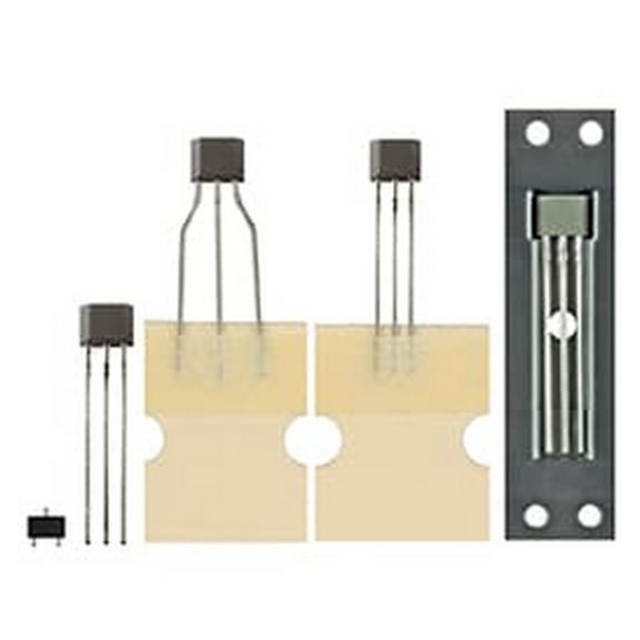
Honeywell describes the SS360NT, SS360ST, and related SS460 variants as latching digital Hall-effect sensor ICs intended for alternating north and south poles. The SS360NT is north-pole operated, while several related variants are south-pole operated. The current family page lists a 3 Vdc to 24 Vdc supply range, -40°C to 150°C operation, digital sinking output, and different SOT-23 and leaded packages.
- Choose latch, unipolar switch, omnipolar switch, linear field, angle, speed, or direction behavior first.
- Use guaranteed operate and release limits across supply and temperature, not a typical sensitivity value alone.
- Confirm which pole sets the output and which pole releases or resets it.
- Check whether the exact variant requires an external pull-up or includes one.
- Prototype with production magnet tolerance, air gap, nearby steel, motor current, vibration, and mounting shift.
Fast analogue observation and networked DC measurement are different jobs
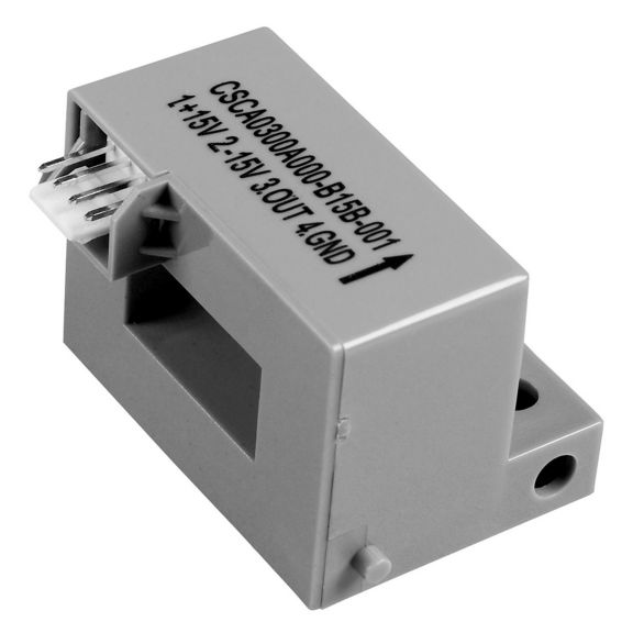
Honeywell's CSCA-A page describes an open-loop Hall family for AC, DC, and impulse current, with listed family ranges from ±150 A to ±900 A, voltage output, and 3 µs or 7 µs response options.
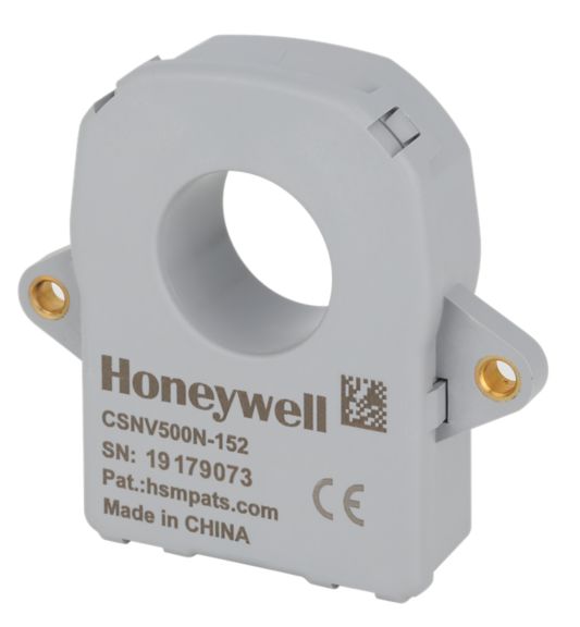
The CSNV500 page describes a closed-loop ±500 A DC family with CAN output and a listed 10,000 µs response time. That is not a simple “fast versus accurate” ranking: waveform, interface, calibration, diagnostics, aperture, network, isolation conditions, and fault response differ.
Safety boundary: a headline isolation test value does not certify the PCB or finished system. Verify test conditions, working voltage, creepage, clearance, pollution degree, material group, layout, enclosure, and applicable standard.
Uncompensated force sensing transfers responsibility into the product
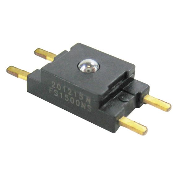
Honeywell's FSS page lists variants from 0 N to 5 N through 0 N to 20 N and describes the family as uncompensated and unamplified. The system therefore owns stable bridge excitation, low-noise amplification, offset and span, temperature characterization, mechanical preload, off-axis control, overforce stop, creep, hysteresis, production calibration, and replacement consistency.
A conditioned force sensor can reduce downstream work even if the bare sensing element appears less expensive. Compare total channel cost, not only component unit price.
Media, manufacturing, safety, and lifecycle need separate evidence
- Freeze the exact orderable part number and document set. Record datasheet and ordering-guide revision, package drawing, interface documentation, application notes, product status, and approved deviations.
- Test the real assembly. Use the production PCB, pressure port, magnet, busbar, actuator, cable, connector, enclosure, firmware, and intended manufacturing process. Evaluation boards are learning tools, not automatic qualification evidence.
- Cover environmental corners. Test minimum, nominal, and maximum supply; input range; temperature; humidity; shock; vibration; contamination; EMC; and representative media or cleaning conditions.
- Exercise fault and recovery states. Include missing sensor, open/short wiring, out-of-range input, bus timeout, stale but plausible data, diagnostic flags, overload, power cycling, CRC or communication errors, and replacement.
- Separate component evidence from system approval. Medical, automotive, aerospace, hazardous-location, or functional-safety requirements can demand controlled processes, diagnostics, traceability, change notification, and system-level analysis.
- Recheck commercial continuity. Confirm lifecycle, product-change and discontinuance notices, authorized or approved channel, traceability, country restrictions, packaging, storage, date-code policy, MOQ, lead time, and redesign plan.
Assembly tests
Zero shift, span, cycling, tubing, port stress, condensation, media exposure, overload, and recovery.
Tolerance tests
Air gap, pole, temperature, target speed, magnet aging, nearby steel, external fields, and mounting shift.
Dynamic tests
Offset, gain, bandwidth, overload, conductor position, thermal rise, external fields, isolation layout, and fault timing.
Mechanical tests
Alignment, preload, stop, creep, hysteresis, thermal coupling, self-heating, response, and fixture repeatability.
Troubleshoot the shortlist, then send a complete RFQ
| Observed symptom | Likely selection gap | Next evidence |
|---|---|---|
| Output saturates at startup | Continuous range was written; transient peak was not. | Measure the transient and compare full scale, proof, burst, overload, and recovery. |
| Pressure zero moves after assembly | PCB, port, tubing, reflow, mounting, or media stress was omitted. | Repeat zero and span before and after each assembly and environmental step. |
| Digital readings arrive too late | Update rate was treated as end-to-end response. | Measure command, conversion, filter, bus, queue, and software age. |
| Hall output has the wrong state | Pole, latch, polarity, or pull-up behavior was misunderstood. | Confirm the exact variant, target motion, thresholds, magnet orientation, and output circuit. |
| Current sensor misses a fault pulse | Bandwidth, saturation, or total protection delay was not qualified. | Compare pulse duration with sensor, interface, software, and actuator latency. |
| Force readings vary by assembly | Load is off-axis or preload, stop, or mounting stress is uncontrolled. | Inspect contact geometry and repeat calibration on production fixtures. |
| Supplier quote omits option characters | A series name was sent instead of the full orderable code. | Require the complete manufacturer part number and decode every option. |
Honeywell sensor RFQ checklist
- Measurand, intended decision, continuous range, minimum useful signal, transients, reverse input, overload, and fault conditions.
- Allowable error over the stated temperature range, response or bandwidth, resolution, update behavior, diagnostics, and calibration plan.
- Output, protocol, supply, valid signal window, pull-up, address, timing, CAN ID/bitrate/termination, and software fault behavior.
- Media, reference, port, magnet or target geometry, conductor and aperture, force contact, package, connector, cable, mounting, ingress, EMC, shock, and vibration.
- Applicable safety and regulatory process, required compliance documents, qualification reports, material declarations, traceability, and change-notification needs.
- Full Honeywell order code, annual volume, prototype quantity, packaging, lifecycle window, date-code policy, storage, delivery need, and approved-alternate rules.
Ask the supplier to return the exact part number, current datasheet, ordering-code breakdown, lifecycle status, deviations, origin or traceability evidence required by contract, packaging, MOQ, and lead time. Any alternative should receive a side-by-side technical comparison and formal engineering approval.
Send the sensor requirement with the part request
YURUNOX is an electronic-component sourcing partner, not the sensor manufacturer or design-approval authority. A complete requirement helps separate sourcing availability from engineering equivalence and highlights where the exact Honeywell configuration still needs validation.
Honeywell sensor selection FAQs
What is the first step in selecting a Honeywell sensor?
Define the physical quantity and the decision the measurement supports. Then write the full input range, transients, environment, allowable error, timing, interface, mechanics, safety, and lifecycle requirements before filtering Honeywell families.
How much sensor range margin should I add?
There is no universal percentage. Use measured or defensible maximum input, startup and fault transients, reverse conditions, and the exact proof, burst, overload, or overforce limits. Preserve adequate resolution and error margin at the smallest useful signal.
What is total error band in a sensor datasheet?
Total error band is a manufacturer-defined combined performance limit over stated conditions. It may include offset, span, nonlinearity, hysteresis, repeatability, and temperature effects. Read the exact definition so included terms are not omitted or counted twice.
Should I choose an analogue or digital Honeywell pressure sensor?
Choose from the complete architecture. Analogue output can suit an existing ADC and continuous path. I2C or SPI can reduce analogue conditioning and deliver calibrated data, but still requires compatible voltage, timing, commands, update behavior, software, and fault handling.
What is the difference between a Hall switch and a Hall latch?
A switch changes state when its magnetic threshold is crossed and returns according to its release behavior. A latch is set by one magnetic pole and reset by the opposite pole. Confirm polarity, thresholds, output circuit, air gap, and target movement for the exact part.
Can one Honeywell current sensor measure AC and DC?
Some can. Honeywell describes the CSCA-A open-loop Hall family for AC, DC, and impulse current. Other products target DC or threshold detection. Verify waveform, frequency content, range, response, output, offset, and isolation conditions in the exact datasheet.
Does a 5 kV isolation value make the finished system safe?
No. A component isolation value has specified test conditions. Finished-system safety also depends on working voltage, insulation coordination, creepage, clearance, pollution degree, PCB layout, enclosure, applicable standards, and fault analysis.
Can I approve a Honeywell sensor from the series page alone?
No. Use the series page to screen candidates, then approve the complete orderable part from its current datasheet, ordering guide, mechanical drawing, lifecycle record, compliance evidence, approved sourcing path, and application qualification results.
Technical sources
Product pages, datasheets, application notes, lifecycle, certifications, and ordering options can change. The values below are screening references reviewed August 27, 2026. Recheck the live manufacturer record and exact orderable part before design release or purchase.
- Honeywell Sensing Solutions — current category and product-finder context.
- Honeywell Pressure Sensors — board-mount and heavy-duty pressure architectures.
- Basic ABP2 Series and MicroPressure MPR Series — pressure, output, compensation, error-band, media, and timing screening data.
- Liquid Level Height Sensing technical note and Solutions for Infusion Pumps — published design situations, not independent outcomes.
- SS360NT/SS360ST/SS460S family and Hall sensors for brushless DC motors — latch behavior, polarity, packages, output, and motor-selection considerations.
- CSCA-A Series and CSNV500 Series — current architecture, range, output, and response screening data.
- FSS Series Force Sensors — force range, package, uncompensated bridge architecture, and exact-order-code examples.