

How to Evaluate an IC Replacement
A cross-reference finds candidates. Only an application-specific evidence review can release one into production.
Short answer: define what the existing circuit truly requires, compare the exact orderable parts and controlled documents, classify every difference as Pass, Conditional, Fail or Unknown, then validate the candidate on production-intent hardware at the relevant electrical, thermal, software and manufacturing corners.


Start by naming the kind of replacement
“Equivalent” is too vague for an engineering change. Decide which outcome is being requested before anyone compares parameters.
No design change
Same footprint, behavior and applicable requirements across the full envelope, with no hardware or firmware change.
Controlled restriction
Usable only with a named BOM value, firmware version, PCB revision, factory, operating limit or temporary deviation.
Engineering migration
Candidate can meet the system goal after schematic, layout, code, qualification or manufacturing changes.
Requirement not met
A non-negotiable limit fails, evidence is not obtainable, or the residual product risk is unacceptable.
Write down what the board asks the IC to survive and deliver
A data sheet describes device capability. The schematic, layout, firmware, enclosure, load and mission profile define the actual requirement. Capture normal operation, production variation and credible abnormal conditions before opening the candidate data sheet.
Separate requirements into must match, must not be worse than a limit, and performance to characterize. This stops a team from rejecting a harmless difference while overlooking a decisive one. A 10 MHz op-amp bandwidth may be irrelevant in a 2 Hz sensor channel; input bias, output recovery or phase reversal may not be.
Make every delta visible, owned and resolvable
Use exact manufacturer part numbers including package and grade suffixes. Link the current data sheets, package drawings, errata, programming guides, qualification summaries, PCNs and supplier evidence. Record document revisions and access dates.
| Matrix field | Question | Decision rule |
|---|---|---|
| Requirement | What must the circuit or product achieve? | Use a measurable system limit, not “same as original.” |
| Original | What is the guaranteed limit and under which conditions? | Record min/max, supply, load, temperature, note and revision. |
| Candidate | Is the specification category and test condition comparable? | Never compare one part’s typical value with another part’s guaranteed limit. |
| Delta | Does the difference reduce margin or change behavior? | Explain direction and product consequence, not just the numeric gap. |
| Status | Pass, Conditional, Fail or Unknown? | Unknown stays open; Conditional names the action and owner. |
| Closure | What evidence will resolve it? | Manufacturer clarification, analysis, simulation, measurement or design change. |
Example rows from an illustrative review
| Parameter | Design need | Candidate evidence | Decision |
|---|---|---|---|
| Enable high | Controller guarantees 1.8 V at cold | VIH(max) = 2.0 V | Fail unless the interface changes |
| Propagation | 15 ns maximum budget | 12 ns maximum under matching load and temperature | Pass |
| Sleep current | 8 µA maximum budget | 5 µA typical; no maximum shown | Unknown — obtain a limit or validate statistically |
| QFN pad | Released copper and stencil | Same package label, different exposed-pad dimensions | Conditional — PCB and assembly review |
Illustrative numbers only; they are not a YURUNOX customer result or a substitute for the two exact device documents.
Verify every pin, pad and assembly interface
Compare each pin by number and behavior: input/output direction, analog or digital function, open-drain or push-pull structure, default pulls, power domain, unpowered tolerance, clamps, reset state, multiplexing and unused-pin instructions. “NC” can mean no internal connection, do not connect or reserved; follow the candidate document.
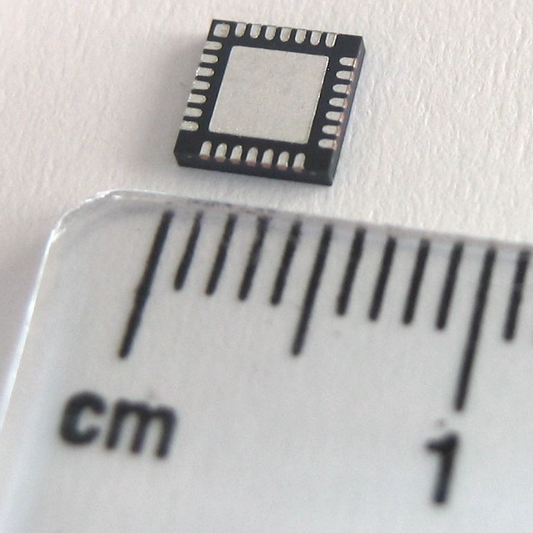
Then compare manufacturer package drawings—not the marketing name. Confirm pitch, body, terminal and ball positions, pin 1, height, coplanarity, standoff, exposed pad, terminal finish, wettable-flank option, land pattern, stencil and thermal-via guidance.
- Overlay the two pin tables and BGA ball maps.
- Compare copper, solder-mask and paste dimensions.
- Check MSL, dry-pack, peak reflow and allowable cycles.
- Confirm AOI, X-ray, programming and rework capability.
- Recalculate heat flow when pad or package construction changes.

Read specifications by category and condition
| Data-sheet item | What it means | Replacement rule |
|---|---|---|
| Absolute maximum | Stress boundary; operation and performance are not implied | Never use as the normal target range. |
| Recommended condition | Range in which operation is intended | Keep the complete application envelope inside it with margin. |
| Guaranteed min/max | Production limit for a stated grade and test condition | Use for worst-case pass/fail when conditions match. |
| Typical value | Representative nominal behavior | Use for estimates, not a worst-case approval by itself. |
| Characterization curve | Trend from characterized devices | Understand sensitivity and validate critical extrapolation. |
Check the whole power sequence
Review supply range, pin current, injection, sequencing, ramp, UVLO, inrush, reverse current, current limit, short circuit, power-off leakage and externally driven pins while unpowered. A candidate can pass steady state and fail only during brownout or hot plug.
Calculate timing and logic margins
NML = VIL(max) − VOL(max)Repeat at the real output current, rail and temperature. Include hysteresis, slow-input limits and overshoot clamps.
Screen thermal margin carefully
At 70°C ambient and 0.8 W, 55°C/W screens to 114°C. A 70°C/W candidate screens to 126°C—a 12°C increase before measurement uncertainty and local heating. That delta deserves a board-level model or test.
Check the failure mode of “better” parts
Faster edges can increase ringing and EMI. Stronger drivers can worsen ground bounce. Lower-ESR capacitors can destabilize an older regulator loop. A lower current limit may protect the IC while preventing a motor, radio or capacitive rail from starting.
Same-looking parts can fail for different reasons
These examples come from manufacturer documentation. They are not YURUNOX field-test claims or invented customer outcomes.
74HC and 74HCT: shared functions, different input assumptions
Nexperia’s Logic Application Handbook explains that the “T” identifies families optimized for TTL input levels. Its 74HC1G14/74HCT1G14 page describes HC inputs as CMOS-level and HCT inputs as TTL-level; it also lists different operating supply ranges. A familiar function and package therefore do not make the logic interface interchangeable.
- Hidden delta
- VIH/VIL and permitted VCC can change while the Boolean function and pin arrangement look the same.
- Engineering action
- Calculate noise margin from the driving device’s guaranteed VOH/VOL at the real load and temperature; check slow-input behavior and power-off conditions.
- Decision consequence
- A board may work at nominal voltage yet lose high-level margin at cold, low rail or high output current.
Nexperia Logic Application Handbook · 74HC1G14 / 74HCT1G14 product page
Pin-identical clamping amplifiers are not automatically drop-in
Analog Devices AN-402 compares output-clamping and input-clamping op-amp architectures. It states that, except for gain-of-one circuits, substituting the input-clamping architecture is not a drop-in replacement even when the pinouts are identical. Overdrive and inverting-mode behavior change because the internal architecture changes.
- Hidden delta
- Architecture and overload behavior—not footprint—control the system response.
- Engineering action
- Review gain configuration, clamp region, input/output range, stability, overload recovery and downstream tolerance; then test the actual signal extremes.
- Decision consequence
- A candidate can be mechanically perfect and electrically powered yet violate the intended clamp or recovery behavior.
Software, qualification and lifecycle are independent approval gates
Software and configuration
For digital and mixed-signal devices, compare register addresses, reset values, reserved-bit rules, write sequences, IDs, calibration storage, interrupts, FIFO behavior, boot straps, programming tools, firmware images, drivers, diagnostics, security features and errata. “Register compatible” should be proven by a line-by-line map and regression plan.
Firmware may compensate for initialization, scaling, timing or device detection. It cannot safely fix a violated voltage limit, inadequate thermal margin, unstable loop, incompatible output structure or physical package mismatch.
Quality and compliance
Confirm that evidence applies to the exact die, package, grade and suffix. AEC-Q100 is a component-level stress-test qualification framework for integrated circuits used in harsh automotive environments; it is not an end-system certification and does not replace application validation.
Check operating grade, MSL, reflow, ESD and latch-up classifications, endurance or retention, substance declarations, functional-safety support, cybersecurity documents and market-specific certificates. Compare test standards and classes exactly; “ESD protected” is not a common unit.
Replacement evidence planner
Choose the device class and change driver. The result is a planning checklist—not an engineering approval.
Validate margin, not merely power-on
Use production-intent PCB revision, BOM, firmware, programming, enclosure, cooling, cables, loads, power supplies and solder process. Define pass/fail limits before testing. The sample size and stress severity must follow failure consequence, variability, mission profile and quality requirements; one working board proves possibility, not repeatability.
Functional tests can miss unstable loops, narrow timing margin, excess jitter, ringing, EMI and latent thermal problems. Add signal-integrity, thermal and pre-compliance checks where the delta or failure consequence justifies them.


A technical pass can still fail the supply gate
Confirm manufacturer lifecycle status, authorized or approved source, date/lot traceability, storage and dry-pack needs, counterfeit controls, warranty path, lead time, allocation exposure, and the route for PCN and EOL notices. TI says notifiable PCNs cover major changes affecting form, fit, function, quality or reliability and include affected products, impact, qualification information, samples and projected shipment timing.
Longevity programs also require exact reading. NXP notes that participating products may move factories after requalification or require migration to a form-fit-function-compatible product. ST states that significant volume or manufacturing changes can lead to a comparable product, technology or facility under its notification policy. Record the exact covered part and program terms rather than treating a family logo as an unconditional guarantee.
A believable cross-reference, but no guaranteed sleep-current maximum
The candidate shows lower typical current and powers the prototype successfully. The product must meet a long standby requirement, yet the candidate data sheet gives no production maximum.
Correct action: keep the row Unknown, request a guaranteed limit or statistically adequate evidence, and include hot/cold and lot variation in the validation plan.
Avoided consequence: nominal battery-life success becoming a production-tail failure.
The base part matches, but the suffix does not
A quote shortens the requested MPN and omits package, temperature or qualification suffixes. Price looks comparable, but the document set does not identify the exact orderable product.
Correct action: pause the quote until the full manufacturer MPN, packing, label evidence, current data sheet, lifecycle status and approved source are aligned.
Avoided consequence: qualifying one device and buying another.
What to include in the RFQ
| RFQ block | Buyer provides | Supplier response requested |
|---|---|---|
| Identity | Original and candidate full MPNs; acceptable alternates explicitly named | Quoted full MPN, manufacturer, packaging and label example |
| Application | Function, rails, load, timing, temperature, mission profile and production horizon | Known-difference statement and unsupported parameters |
| Documents | Required data-sheet, package and quality revision baseline | Current controlled documents, errata and qualification evidence |
| Source | Approved-channel and traceability requirements | Source path, lot/date-code evidence, CoC and warranty route |
| Lifecycle | Annual volume, launch, service obligation and PCN contacts | Status, lead time, allocation exposure and PCN/EOL process |
Send the exact parts and the application envelope
YURUNOX can support sourcing evidence collection and quote comparison. Final circuit compatibility and product approval remain with the responsible engineering and quality teams.
Request an IC replacement reviewIC replacement FAQ
Is a pin-to-pin replacement enough?
No. Pin alignment is only one dimension. Pin behavior, electrical limits, timing, package geometry, thermal performance, protections, software, qualification and lifecycle can still differ. Treat pin-to-pin as a reason to investigate, not as approval.
Can typical specifications approve an IC replacement?
Not for a worst-case requirement unless the manufacturer guarantees the value under the required conditions or a controlled validation plan supplies adequate evidence. Typical values describe nominal behavior, not production limits.
Is a higher absolute maximum rating always better?
No. Absolute maximum ratings are stress boundaries. A candidate can survive a higher voltage yet have a narrower recommended range, worse accuracy, different clamps, higher leakage or unsuitable transient behavior.
Does the same package name mean the PCB can stay unchanged?
No. Compare exact package drawings and manufacturer land-pattern guidance. Exposed-pad size, terminal geometry, height, pin-1 orientation, paste pattern, thermal vias, wettable flanks and ball maps can differ.
How many prototypes should be tested?
Use a risk-based plan based on failure consequence, parameter variability, critical deltas, mission profile, manufacturing variation and regulatory or customer requirements. One successful board demonstrates possibility, not repeatability or margin.
When can an IC be called a drop-in replacement?
Only when it needs no hardware or software change and meets every applicable requirement across the defined application, manufacturing, quality and lifecycle envelope. If a restriction remains, label it conditional instead.
What documents should a replacement supplier provide?
Request the current manufacturer data sheet, package drawing, known-difference statement, qualification evidence, material and MSL information, errata, lifecycle status, PCN/EOL policy and source traceability. Critical applications may need site, process, safety, security or detailed reliability evidence.
Can firmware compensate for hardware differences?
Sometimes for initialization, timing, calibration or device detection. Firmware cannot safely overcome violated voltage limits, inadequate thermal margin, unstable analog loops, incompatible output structures, insufficient timing margin or a physical package mismatch.
Technical references
- Texas Instruments — Cross-reference search: automated-tool limitations and user responsibility for selection, design, validation and testing.
- Texas Instruments — Semiconductor and IC Package Thermal Metrics, Rev. D: correct interpretation and system dependence of package thermal metrics.
- Texas Instruments — SMT and packaging application notes: manufacturer guidance for land patterns, attachment, thermal design and rework.
- Nexperia — Logic Application Handbook and 74HC1G14 / 74HCT1G14: HC/HCT input-level and supply differences.
- Analog Devices — AN-402: a documented pin-identical op-amp architecture substitution that is not generally drop-in.
- Automotive Electronics Council — AEC documents: current component qualification documents including AEC-Q100.
- Texas Instruments — Product change notification: PCN scope, contents and product-withdrawal handling.
- NXP — Product Longevity and STMicroelectronics — Product Longevity: program conditions, manufacturing changes and migration provisions.
Sources reviewed 28 August 2026. Recheck exact data sheets, drawings, errata, qualification reports, lifecycle pages, PCNs, orderable suffixes and supplier authorization before making an engineering or purchasing decision. Formula and scenario values above are illustrative screens, not test results.