

Honeywell Hall Sensor Selection Guide
Choose the sensing function first: a digital switch for position, a latch for alternating poles, a linear Hall IC for field or displacement, or a current-sensor assembly for current. Then qualify the exact orderable part against guaranteed magnetic thresholds, timing, output, package and temperature.
A family name alone is not a design rule. The magnet, air gap, alignment, supply, pull-up, sampling behavior and mechanical tolerances form one sensing system.
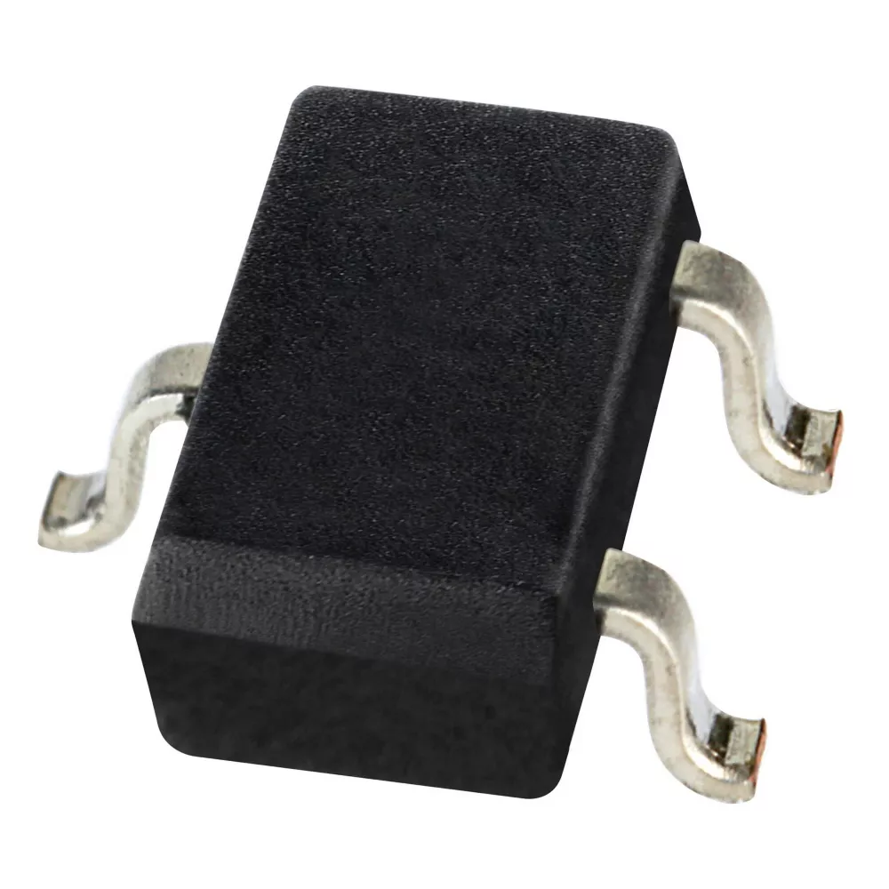
Pass five gates before comparing part numbers
Start with what the controller must know. Next define the pole behavior. Then prove the weakest installed magnet still crosses the guaranteed operate and release limits. Only after that should you compare voltage, current, response, output circuit, package, qualification and price.
This order prevents a common purchasing failure: finding a device with a familiar package and voltage, then discovering that it detects the wrong pole, sleeps through a short event, needs an external pull-up or cannot meet the magnetic margin at the largest production air gap.
Hall is not a synonym for every magnetic sensor
Honeywell's SL353 devices are micropower omnipolar Hall-effect sensor ICs. The SM351LT and SM353LT are nanopower omnipolar AMR sensor ICs. AMR may be attractive when very low field thresholds or supply current matter, but it is a different sensing technology. Keep the distinction visible in schematics, approved-vendor lists and RFQs.
What must the sensor report?
Scroll sideways to compare the sensing functions →
| Required information | Typical architecture | Honeywell examples to investigate | Question that eliminates wrong choices |
|---|---|---|---|
| Open / closed or present / absent | Digital Hall or AMR switch | SL353; SS351AT / SS451A / SS551AT; SS341RT / SS441R; SM351LT / SM353LT | Must one specified pole activate it, or may either pole activate it? |
| Rotor position from alternating poles | Digital latching Hall switch | SS360 / SS460; VF360NT / VF360ST / VF460S | Which pole sets the output and which pole resets it? |
| Field strength or displacement | Ratiometric linear Hall IC | SS39ET / SS49E / SS59ET; SS490 family | Does the worst-case output remain inside the ADC range with useful resolution? |
| Current in a conductor | Hall element plus magnetic path and calibrated assembly | CSLA family and other current-sensor platforms | What current range, conductor geometry, bandwidth, offset and isolation are required? |
| Industrial installed position | Packaged magnetic sensor | 103SR, SR16 and SR17 families | Do housing, termination, ingress, mounting distance and target magnet fit? |
A digital switch answers a threshold question. A linear part produces a continuous voltage related to field. A current sensor is a complete magnetic measurement channel, not merely a position-switch IC placed near a wire. These categories are not interchangeable even when the words “Hall effect” appear on every datasheet.
Define the logic event in plain language
Write a sentence such as: “The output shall go low when either magnetic pole is close enough, and return high after the magnet moves away.” That sentence suggests an omnipolar switch with an appropriate output circuit. “The output shall stay active after a north pole passes and reset only when a south pole passes” instead describes a latch.
BOP starts the event; BRP ends it
BOP is the operate point at which the sensor changes state as field increases. BRP is the release point at which it returns as field decreases. The difference creates hysteresis, which helps prevent chatter when vibration or noise moves the field around a threshold.
A result above 1 is necessary, but it is not system proof. Include temperature, magnet tolerance, ageing assumptions, gap, lateral offset, rotation, nearby steel and sensor-position tolerance.
A 160 G minimum field versus a 135 G maximum BOP
Suppose a magnetic stack-up model predicts at least 160 G at the sensor in the worst installed position. If the chosen exact part has a maximum operate threshold of 135 G under the relevant polarity and conditions, the simple screening ratio is 160 / 135 = 1.19.
That 19% numerical headroom is only an initial screen. The design still needs tolerance analysis and prototype measurements at minimum and maximum temperature. Release must also be checked: excessive residual field may keep a switch active after the mechanism moves away.
Scroll sideways to review the behavior definitions →
| Behavior | Activation | Release / reset | Typical use |
|---|---|---|---|
| Unipolar switch | One specified pole reaches BOP | Field falls through BRP | Position with controlled magnet orientation |
| Omnipolar switch | Either north or south field reaches its threshold | Magnitude falls below the corresponding release limit | Lids, doors and presence sensing where assembly polarity may vary |
| Bipolar switch | Behavior can depend on pole and magnetic history | Review the exact transfer table | Applications designed around two-pole behavior |
| Latch | One pole sets the output | Opposite pole resets it | BLDC commutation, speed and rotary position |
Do not build production margin from a typical threshold. Typical values help modeling; guaranteed minimum and maximum limits determine acceptance. Also preserve units: 1 mT = 10 G. A unit mistake can move the design by a factor of ten.
Build a family-level shortlist
This tool identifies an architecture and example families to investigate. It does not verify an exact suffix, threshold, package, qualification or lifecycle status.
Polarity, power mode and output can change the shortlist
Scroll sideways to see all family notes →
| Family | Behavior | Notable starting data | Selection consequence |
|---|---|---|---|
| SL353LT / SL353HT | Micropower omnipolar Hall, push-pull | 2.2 V to 5.5 V; ±60 G typical operate point. LT: 1.8 µA typical; HT: 0.33 mA typical. | LT favors average power; HT's higher duty cycle favors faster/repeated events. Typical field is not the guaranteed design limit. |
| SM351LT / SM353LT | Nanopower omnipolar AMR, push-pull | SM351LT: 7 G typical, 11 G maximum; SM353LT: 14 G typical, 20 G maximum; low-voltage operation. | Potentially useful for weak fields and tiny current budgets, but specify AMR rather than calling it a Hall replacement. |
| SS351AT / SS451A / SS551AT | Omnipolar Hall | SOT-23, flat TO-92 and small leaded-package options; broad supply and temperature variants in the family. | Package and output suffixes affect PCB, active area and interface. Do not approve from the shared base number. |
| SS341RT / SS441R | Unipolar Hall | Designed for one-pole actuation with surface-mount and leaded options. | Useful when magnet polarity is controlled; an accidental pole reversal can prevent operation. |
| SS360 / SS460 | Latching Hall | Alternating north/south fields set and reset the state. | Match pole sequence, BOP/BRP sign convention and package to the rotor geometry. |
| VF360NT / VF360ST / VF460S | AEC-Q100-qualified latching Hall | VF360NT is north-pole activated; VF360ST and VF460S are south-pole activated. Surface-mount and leaded choices. | Automotive qualification belongs to the exact orderable part. Pole suffix is a functional requirement, not a purchasing detail. |
Output topology is part of compatibility
An open-collector output needs a pull-up and normally sinks current when active. A push-pull output actively drives both states. Some families or suffixes include a pull-up while others do not. Confirm logic polarity, output-low voltage, leakage, pull-up rail, input thresholds and power-up behavior before accepting an alternative.
Low power can come with a sampling-time trade-off
A micropower magnetic switch may wake periodically instead of sensing continuously. Average current can be excellent, yet a magnet that enters and leaves between samples may not be captured. Review the datasheet's duty cycle, sample period, operate time and required pulse width, not only the current headline.
LT and HT at a 2.8 V rail
Using Honeywell's typical current figures, SL353LT sensor power is approximately 2.8 V × 1.8 µA = 5.04 µW. SL353HT is approximately 2.8 V × 0.33 mA = 0.924 mW. The ratio is about 183:1.
This does not predict battery life. Pull-up current, MCU wakeups, regulator loss, self-discharge, temperature and event frequency also matter. The higher-current option may still be correct if the event is too short for the low-duty-cycle device.
Convert rotation into magnetic event frequency
Illustrative example: 6 events per revolution at 3,000 rpm produces 300 events per second. Check the complete sensor-to-controller path against 300 Hz plus timing margin.
For a latch, define whether one “event” means one pole transition or a complete north-south cycle. Include rotor speed tolerance, startup, reverse rotation and missing/unequal poles. If the signal feeds commutation or protection, validate total latency rather than the sensor alone.
Linear Hall selection is a range-and-resolution problem
Honeywell's SS39ET / SS49E / SS59ET and SS490 families produce ratiometric analog outputs. At zero field, the output is typically near half the supply. One field direction moves the output higher; the opposite direction moves it lower. Sensitivity determines volts per gauss, while the supply and output swing limit the usable range.
5 V supply, 5 mV/G typical sensitivity
Using typical values only, a 5 V supply gives a 2.5 V null. At +100 G, the estimate is 2.5 V + (100 G × 5 mV/G) = 3.0 V. At −100 G, it is approximately 2.0 V.
Honeywell lists SS494B sensitivity as 4.6 mV/G minimum, 5.0 mV/G typical and 5.4 mV/G maximum on the current product page. A released design must include that spread, null error, output limits, temperature, supply tolerance, ADC reference and mechanical field tolerance.
Higher sensitivity improves voltage change per gauss but reduces field headroom before the output approaches a rail. Lower sensitivity covers a wider field range but gives fewer ADC counts per gauss. Select sensitivity together with the actual magnet range and the smallest displacement or field change that must be resolved.
Use the same reference intentionally
Because a ratiometric output changes with supply, using the sensor supply as the ADC reference can cancel part of the supply variation in a suitable architecture. That does not remove sensor gain error, null drift, noise or regulator transients. Document the reference path and startup sequence.
Air gap, alignment and nearby steel decide the installed field

Model the weakest and strongest field
The magnet drawing, grade and surface field do not state the field at the IC. Simulate or measure the installed condition at the datasheet active area. Sweep gap, lateral offset, tilt, magnet tolerance, sensor placement, housing stack-up and temperature.
Check the strongest field too. A linear sensor can lose usable output headroom, and a nearby magnet or steel bracket can bias the operating window. Screws, shafts and magnetic shielding may redirect flux.
Read the active-area drawing
Two SOT-23 sensors can place the active element at different depths or offsets. A leaded package can bend during assembly. Package outline compatibility does not prove magnetic alignment.
For production validation, build a position-field map rather than testing one nominal point. Measure several magnetic and mechanical tolerance corners, then repeat at temperature. Record both approach and withdrawal so BOP, BRP and hysteresis are visible.
Do not select a current sensor from amperes alone

Define the complete measurement channel
Honeywell's CSLA family combines linear Hall sensing with a magnetic flux path and housing. A buyer must still specify nominal and peak current, direction, overload duration, conductor or aperture geometry, supply, null output, sensitivity, bandwidth, temperature and required isolation.
A Hall position switch beside a conductor is not automatically a calibrated current sensor. Conversely, a current-sensor assembly may contain a Hall transducer but have mechanical and electrical limits that dominate selection.
Separate isolation from magnetic detection
Magnetic coupling can support galvanic isolation, but the approved working voltage depends on the product's insulation construction and ratings. Never infer a safety barrier from the sensing principle alone.
When the application is fundamentally a current-measurement decision, compare Hall architectures with shunts, current transformers and other magnetic methods. Use YURUNOX's purchasing experience page to frame a sourcing enquiry, but keep architecture approval with the design and safety teams.
Two illustrative selection scenarios
A long sleep interval makes sensor current important, but the lid can move quickly
The controller needs a binary “closed” signal and cannot guarantee magnet polarity during service, so an omnipolar switch is the architectural starting point. The team compares the low-average-current SL353LT Hall device with SL353HT and the SM351LT / SM353LT AMR options.
The decision is not “pick the lowest microamps.” The team measures how long the magnet remains inside the guaranteed operate region during the fastest lid movement, then compares that dwell time with each sensor's sampling behavior. It checks the weakest field at maximum gap against maximum BOP, verifies release at the open position, and includes controller and regulator sleep currents in the energy budget.
RFQ evidence: exact Honeywell code, 2.8 V rail, magnet polarity freedom, minimum installed field versus temperature, minimum event duration, output interface, package and annual quantity.
An automotive latch must match the pole sequence and exact qualification
The rotor presents alternating north and south poles, so a latching device is appropriate. If the circuit expects a north pole to activate the output, VF360NT is a candidate; if it expects south-pole activation, VF360ST or VF460S may fit the logic. Swapping the suffix can invert functional behavior even when voltage and package look compatible.
The team converts maximum rpm and pole count into event frequency, verifies BOP and BRP at rotor runout and temperature, and checks power-up behavior before commutation begins. It confirms AEC-Q100 status for the exact orderable part and retains system-level automotive and functional-safety validation separately.
RFQ evidence: required activation pole, package, supply, output circuit, guaranteed thresholds, temperature grade, event rate, qualification requirement, traceability and change-notification terms.

Qualification and RFQ checklist
- Freeze the sensing statement.Presence, latch, proportional field, displacement or current; include logic polarity and what constitutes release.
- Define the magnetic window.Polarity, minimum and maximum field at the active area, gap and alignment stack-up, BOP, BRP, hysteresis and temperature.
- Define electrical compatibility.Supply range and transients, open collector or push-pull, pull-up rail, output limits, ADC range, current budget and power-up state.
- Define timing.Minimum event duration, maximum event rate, response, sampling behavior and end-to-end controller latency.
- Control physical and environmental details.Exact package, active-area location, PCB footprint or leads, mounting, ambient, vibration, ingress and nearby magnetic materials.
- Approve the exact orderable code.Qualification, temperature grade, packing, moisture handling where applicable, lifecycle status, revision and approved alternatives.
For independent sourcing, confirm authenticity and storage evidence as part of the purchasing process. Review YURUNOX's quality assurance and global shipment pages when defining documentation and delivery requirements. Availability does not convert one magnetic function into another.
Send the exact Honeywell code and the selection constraints
Include quantity and required date, plus sensing function, pole behavior, guaranteed magnetic window, supply, output, package, temperature and qualification. If alternatives are allowed, state which limits are fixed and require engineering approval before substitution.
YURUNOX is an independent electronic-component sourcing partner, not the sensor manufacturer. Honeywell controls its product specifications; your engineering team retains responsibility for design release and safety validation.
Honeywell Hall sensor selection FAQ
How do I choose between a unipolar, omnipolar and latching Hall sensor?
Use a unipolar switch when one controlled pole should operate and release with distance. Use an omnipolar switch when either pole may operate it. Use a latch when one pole must set the output and the opposite pole must reset it, as in many rotating-magnet applications. Verify the exact datasheet polarity and threshold signs.
What is the difference between BOP and BRP?
BOP is the magnetic operate point that changes the sensor state as field increases. BRP is the release point as field decreases. Their difference is hysteresis. Use guaranteed limits over the required conditions, and test both approach and withdrawal in the installed mechanism.
Are Honeywell SM351LT and SM353LT Hall sensors?
No. Honeywell identifies SM351LT and SM353LT as nanopower omnipolar magnetoresistive sensor ICs using AMR technology. SL353LT and SL353HT are micropower omnipolar digital Hall-effect sensor ICs. The families can address similar presence-sensing tasks but should not be described as the same technology.
Why can a lower-power Hall sensor miss a short event?
Some micropower devices sample periodically to reduce average current. If the magnetic target enters and leaves the guaranteed operating region between samples, the event may not be detected. Compare minimum target dwell time with the datasheet sampling and response behavior.
Does an open-collector Hall output need a pull-up resistor?
Usually yes, unless the exact device or suffix includes one or the receiving circuit provides a suitable pull-up. Verify the output schematic, pull-up voltage, sink current, leakage, logic thresholds and power-off behavior. A push-pull alternative has a different interface.
Can I replace a Hall switch with another device in the same package?
Not from package alone. Compare sensing function, polarity, guaranteed BOP and BRP, hysteresis, supply, output topology, timing, active-area location, temperature, qualification and power-up behavior. The same SOT-23 outline can contain functionally incompatible sensors.
How much magnetic margin is enough?
There is no universal percentage. The weakest installed field must exceed the maximum guaranteed operate threshold after magnet, mechanical, temperature, ageing and nearby-material tolerances. Release at the opposite mechanical state also needs margin. Validate simulations with corner prototypes.
Is a Hall current sensor automatically galvanically isolated?
No. Magnetic sensing can cross an insulation barrier, but working voltage, creepage, clearance and dielectric ratings depend on the complete product construction. A bare Hall IC or an unrated assembly does not establish system isolation.
Technical references
Manufacturer documentation supports the named families and specifications. Always use the current datasheet and the exact orderable code before design release or substitution approval.
- Honeywell SL353 Series product page — Hall technology, supply, field, current and push-pull output.
- Honeywell Nanopower Series AMR product page — SM351LT / SM353LT technology and thresholds.
- Honeywell SS490 Series product page — ratiometric output, temperature and SS494B sensitivity.
- Honeywell SS39ET / SS49E / SS59ET product page — linear Hall family.
- Honeywell VF360NT / VF360ST / VF460S product page — latching polarity, packages and AEC-Q100 qualification.
- Honeywell CSLA Series linear current-sensor page — current-sensor family architecture and ranges.
- Honeywell Position Sensors Range Guide — family, output, package, supply and application overview.
- Honeywell Magnetics for Battery-Powered Appliances application note — Hall and AMR distinctions in low-power applications.
All calculations and scenarios in this guide are educational and explicitly illustrative. They are not YURUNOX laboratory data, shipment outcomes, customer case studies or design approvals. Honeywell and the product names cited are trademarks of their respective owners.