

NOR Flash vs NAND Flash vs eMMC vs UFS: How to Choose
NOR is usually the starting point when firmware needs direct random reads, execute-in-place, or an independent boot and recovery store. Raw NAND suits high-density storage only when the host owns the required NAND management. eMMC packages NAND with a controller behind a widely supported embedded interface. UFS is managed NAND with a faster serial architecture for hosts and workloads that can use it.
These are architectural choices, not four interchangeable speed grades. Choose by boot path, controller responsibility, real workload, endurance, power-loss behavior and host qualification before comparing price or headline bandwidth.
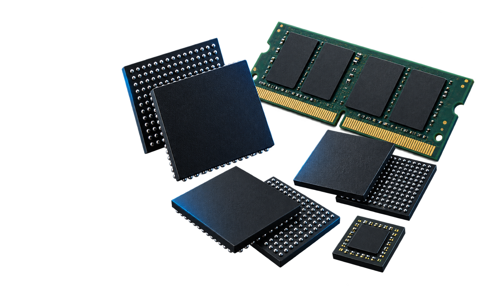
What is the difference between NOR, raw NAND, eMMC and UFS?
NOR and raw NAND describe flash-memory architectures. eMMC and UFS are managed storage devices that normally combine NAND with an internal controller and a standardized host interface. That controller boundary changes the work left to the processor and software.
| Decision factor | NOR Flash | Raw NAND Flash | eMMC | UFS |
|---|---|---|---|---|
| Typical role | Bootloader, firmware, recovery image, parameters and supported XIP designs | High-density storage in a system with a NAND-aware controller | Embedded managed storage for Linux, data and general applications | Higher-performance managed storage for capable mobile, edge and automotive platforms |
| Access model | Fine-grained random reads; erase and program remain device-specific | Page reads/programs and block erases | Logical block device over a parallel eMMC interface | Logical storage over a high-speed serial interface with command queuing |
| Media management | The system manages erase, program, protection and update policy | The host handles ECC, bad blocks, mapping, wear policy and recovery | The internal controller handles core NAND management | The internal controller handles core NAND management |
| Host requirement | A compatible memory controller and boot/read mode | A controller and software matched to the NAND geometry and ECC need | An eMMC host supporting the required mode, boot features and software | A UFS host, matching M-PHY/UniPro support, software and board-level signal integrity |
| Main approval risk | Insufficient image space, wrong read mode or unsafe update design | Unsupported geometry, ECC strength, bad-block policy or die revision | Endurance, sustained writes, boot configuration and uncontrolled product changes | Host compatibility, signal integrity, thermal behavior, workload and revision control |
Swipe or scroll the table on a small screen. These are architecture-level differences; the exact part datasheet and host documentation control the design.
Where does flash-management responsibility sit?
The practical difference is not simply whether a package contains NAND. It is whether the host sees the physical NAND behavior or a managed logical block interface.
NOR Flash
The host uses device commands and owns the firmware layout, erase strategy, protection and update recovery.
Raw NAND
The platform must match page/block geometry, ECC need, bad-block marking and the chosen mapping or filesystem strategy.
eMMC
The package exposes logical storage and manages core media behavior, but the system still owns workload, health monitoring and recovery policy.
UFS
Management is internal, while the host and PCB must support the applicable serial link, protocol stack, lanes and performance modes.

Why is raw NAND support a controller-and-device decision?
A raw NAND quote is incomplete without the host-controller context. Density and package do not reveal the page size, block organization, spare area, supported ECC requirement, interface timing or bad-block conventions.
- Confirm the exact NAND organization and the controller's supported geometry.
- Match the required correction strength and codeword arrangement.
- Preserve the manufacturer's initial bad-block markers before use.
- Validate the bootloader, driver, filesystem or flash-translation layer with the exact device and revision.
KIOXIA's bad-block guidance distinguishes host-managed raw NAND from eMMC/UFS devices that perform bad-block management internally. A managed controller reduces host burden; it does not remove the need to qualify the complete system.
Which storage type fits your system requirement?
Start with the function the memory must perform. The same product can use one device for boot and another for operating-system or user data.
When should you choose NOR Flash?
Choose NOR when directly addressable firmware, fine-grained random reads, execute-in-place or an independent recovery store are primary requirements and the required density is practical. Confirm that the processor boot ROM and memory controller support the exact serial, parallel or xSPI mode.
- Budget the bootloader, active image, fallback image, metadata and future growth.
- Check erase-sector size, write/erase timing and protection behavior.
- Design recovery for interruption during a firmware update.
When does raw NAND make sense?
Use raw NAND when density economics matter and the platform already owns a proven NAND-management stack. It is not the low-effort choice merely because the component price per bit is attractive.
- Confirm controller support for the exact device and die revision.
- Validate ECC, initial and grown bad blocks, wear leveling and recovery.
- Control driver, boot-tool and manufacturing-programming revisions.
When is eMMC the practical choice?
eMMC is often appropriate when an embedded system needs managed, soldered storage and the SoC provides an eMMC host. It can simplify integration compared with raw NAND because the package handles core ECC, wear leveling, mapping and bad-block management, as summarized in KIOXIA's eMMC product brief.
- Verify the supported host mode and boot partitions.
- Model sustained writes, usable capacity, health reporting and service life.
- Define controller, NAND or product-revision change controls for approved parts.
When does UFS justify its added complexity?
UFS is the stronger starting point when the processor supports the required UFS generation and the workload benefits from its serial link, command queuing and simultaneous read/write capability. The higher-performance interface also increases board and software validation demands.
- Match host, UFS generation, M-PHY/UniPro support, lanes and gear.
- Validate signal integrity, power integrity, thermals and sustained behavior.
- Confirm the application actually benefits from queue depth and concurrency.
How should you compare real flash performance?
Interface bandwidth is only a ceiling. Device capacity, NAND generation, controller policy, cache behavior, queue depth, fill level, temperature, background management and the host software can all change the observed result.
Why is a UFS benchmark not a system guarantee?
UFS has an architectural advantage over eMMC for concurrency: separate serial transmit and receive paths support full-duplex operation, and command queuing lets the controller schedule multiple operations. Samsung's interface explanation describes both features. They do not guarantee that every workload or host will run faster.
Samsung's June 2026 UFS 5.0 announcement names up to 10.8 GB/s for its specific solution. Treat that as a product claim under Samsung's conditions, not as the performance of every UFS device or a drop-in promise for an existing design. Read the named announcement.
What should be tested on the actual host?
Measure the behavior that can fail the application, not only a short sequential transfer. Use the intended filesystem, software release, data pattern, fill level, power state and temperature.
- Boot time and first-access latency
- Sustained sequential writes after cache effects
- Small random I/O and relevant queue depths
- Tail latency during background management
- Thermal throttling and power consumption
- Recovery after reset or unsafe power interruption
Compare every candidate under the same host, workload, software and measurement method. A faster interface mode can remain unused if the SoC, board or software does not support it.
How do endurance, bad blocks and power loss change the choice?
Managed storage moves media-management work into the device, but it does not create unlimited write life or automatic recovery from every interruption. The workload and failure response remain system-level responsibilities.
Who owns bad-block management?
Raw NAND can contain manufacturer-marked bad blocks at shipment and can develop additional bad blocks in service. The host must preserve the marking convention, detect failures and map around unusable blocks. eMMC and UFS controllers normally manage bad blocks internally and expose logical storage plus health information defined by the device and applicable standard.
How should write lifetime be estimated?
Begin with host bytes written over the required service life, then account for the write amplification created by garbage collection, metadata and the actual write pattern. Compare the result with the selected manufacturer's device-specific endurance method and conditions. Capacity, NAND cell type or program/erase cycles alone are not a complete lifetime model. KIOXIA's lifetime-reliability brief explains the TBW, WAF and NAND-endurance relationship.
Useful relationship: estimated NAND writes = host writes × write amplification factor. Small random updates can produce a different factor from large sequential writes; measure or obtain a justified value for the real workload.
What must survive a power interruption?
Test cuts during the operations that matter: firmware update, partition change, filesystem metadata update, sustained logging and background management. Define the required result after restart, such as a valid fallback image, mountable filesystem, bounded data loss or a detectable fault. A power-loss-protection claim must be tied to the exact device and test condition.
What does the Tesla eMMC recall demonstrate?
NHTSA recall 21V-035 documents certain Tesla Model S and Model X vehicles with an 8 GB eMMC in the media control unit that could malfunction from accumulated wear. The service action combined newer software with replacement by an upgraded 64 GB component. The case shows why write volume, health warning, software behavior and service strategy must be considered together.
This is an official public recall record, not a YURUNOX customer case and not evidence that capacity alone determines endurance. Read the NHTSA-hosted service bulletin.
When should a design use more than one flash device?
“NOR or eMMC” can be the wrong question. A system may keep boot or recovery code in NOR while using raw NAND, eMMC or UFS for the operating system and bulk data.
Why can NOR and eMMC appear together?
Each device can have a different trust and recovery role. NOR can provide an early boot stage or fallback path that is independent of the managed storage. eMMC can provide larger logical storage for the operating system, applications and data.
TI's AM62x starter-kit documentation identifies both OSPI flash and eMMC and documents boot configurations for those media. It is a public development-platform example, not a universal requirement for AM62x products or a substitute for the board designer's boot plan.
Review the TI AM62x starter-kit guide.When is a split architecture worth the extra device?
Use an additional memory only when it creates a defined benefit that the system will verify.
- A recovery image must remain available after a failed update.
- The boot ROM supports one medium while bulk storage uses another.
- Security, update ownership or field-service policy requires separation.
- The main storage may be replaced or requalified without changing the immutable boot path.
Include the extra BOM cost, board area, programming steps and lifecycle exposure in the decision. Infineon's NOR guidance describes A/B image and XIP arrangements for reliable firmware updates; the required capacity and security flow remain product-specific.
What must be verified before replacing one flash device with another?
A matching capacity, package footprint or newer interface mode makes a device a candidate, not an approved substitute. Compare the complete orderable part and the system assumptions in the direction you intend to replace it.
| Review area | What must match or be approved | Evidence to retain | Hold condition |
|---|---|---|---|
| Identity and package | Manufacturer, full MPN, density, organization, package drawing, pinout, temperature grade and packing suffix | Exact datasheets, package drawings and quoted full code | Any unexplained suffix, package or pin difference |
| Host interface | Voltage, bus width or lanes, supported generation/mode, timing, boot-ROM and driver support | Host documentation plus device-specific interface limits | The host cannot be shown to support the offered configuration |
| Media behavior | NAND geometry, ECC requirement, bad-block method, managed features, partitions and health reporting | Controller compatibility record and configuration comparison | Management responsibility or required feature remains undefined |
| Performance and life | Boot time, real workload, sustained behavior, endurance assumptions, retention and temperature | Same-condition test plan and results tied to the sample revision | Approval relies only on headline speed or nominal capacity |
| Power and recovery | Current, power states, reset, unsafe-cut behavior, update rollback and corruption response | Applicable datasheet limits and system interruption tests | The required recovery outcome is not defined or demonstrated |
| Change control | NAND die, controller, firmware and product-revision policy; PCN expectations and requalification owner | Supplier/manufacturer change record and written approval path | An offered revision can change without the agreed review |
This table qualifies a candidate for review; it does not certify interchangeability. Production approval belongs to the design owner and the applicable quality process.
What should engineering and purchasing send in the RFQ?
A useful request lets suppliers quote the same technical requirement that engineering intends to approve. Do not separate the commercial line item from the host and workload that make it acceptable.
Manufacturer, complete MPN, storage type, capacity, organization, package and temperature grade.
SoC, supported interface generation or mode, boot source, XIP need, partitions and recovery path.
Daily writes, transfer pattern, queue depth, fill level, sustained performance, service years and retention.
Power-loss behavior, thermals, health monitoring, security features and required system tests.
Restrictions on die, controller, firmware or product revisions; PCN route and alternate-approval owner.
Quantity, required date, destination, packaging, labels, lot expectations, traceability and inspection scope.
Source the architecture the system has actually approved
YURUNOX is an independent electronic-component sourcing partner. Share the exact part number or target function together with the host, boot path, workload and evidence requirements so a near-match is not mistaken for an approved replacement.
- Full MPN and quantity
- Host and interface mode
- Boot and workload requirements
- Alternate and evidence policy
Technical sources and scope
Manufacturer and public-agency sources support the architecture, endurance and named-case statements. Product-specific claims remain limited to the named device or platform and its stated conditions.
- Infineon: NOR Flash — random-read and execute-in-place architecture guidance.
- Infineon: NOR Flash for reliable FOTA — image storage, XIP and update arrangements.
- KIOXIA: e-MMC Managed Flash — internal controller functions and host-interface considerations.
- KIOXIA: Understanding Bad Block Management — raw NAND versus managed-device responsibility.
- KIOXIA: TBW, WAF and NAND Endurance — workload and write-amplification model.
- Samsung Semiconductor: UFS performance architecture — serial full-duplex paths and command queuing.
- Samsung: named UFS 5.0 announcement — June 2026 product-specific bandwidth claim.
- Texas Instruments: AM62x Starter Kit User's Guide — documented OSPI flash and eMMC hardware example.
- NHTSA: Recall 21V-035 service bulletin — documented 8 GB eMMC accumulated-wear case and service action.
The worked replacement scenario is illustrative, not a YURUNOX shipment, customer result or automatic approval. YURUNOX is not the manufacturer of the cited storage products.