

Visual Inspection vs X-Ray vs Electrical Testing for ICs
Visual inspection checks the outside. X-ray examines internal construction. Electrical testing checks selected performance under defined conditions. These methods complement one another; none alone proves that an integrated circuit is genuine or suitable for your application.
For an incoming IC lot, choose the inspection scope from the source history, exact part, application risk and customer requirements. Then connect every result to the material you will actually receive.
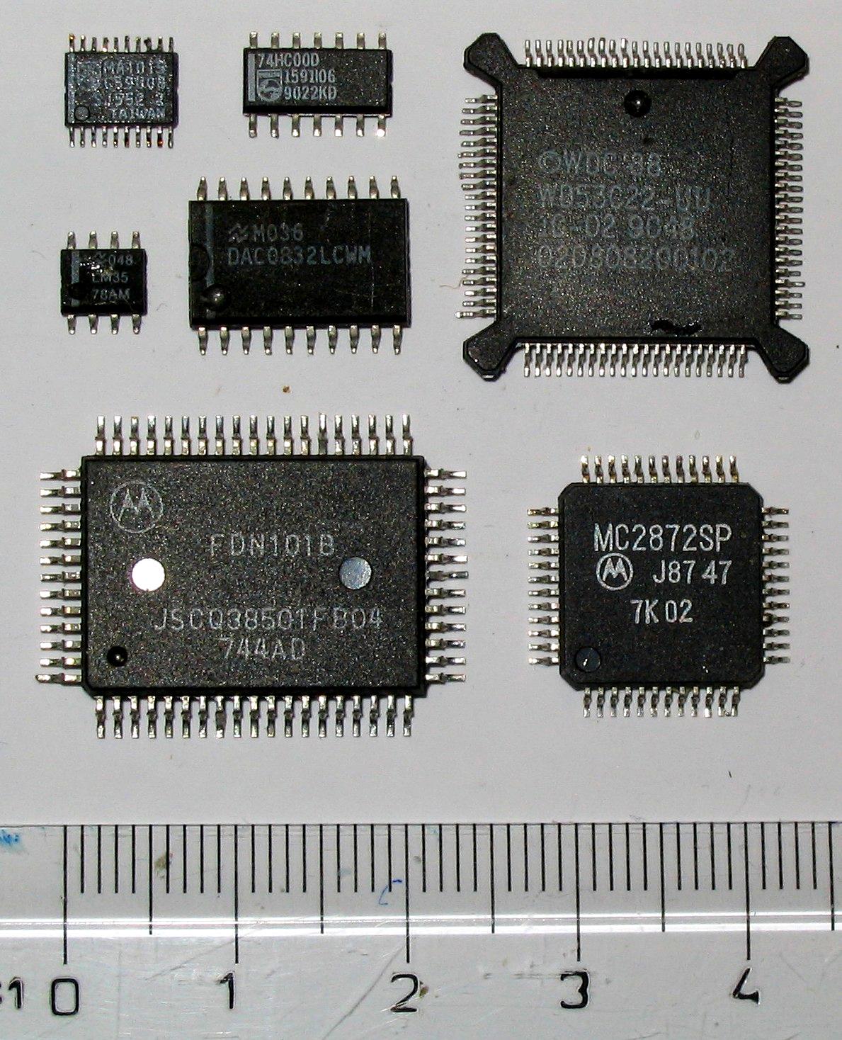
What Is the Difference Between Visual Inspection, X-Ray and Electrical Testing?
The difference is the question each method answers. A clear marking is not an electrical result, a matching radiograph is not a source record, and a functional pass does not explain an altered package.
| Method | What it can reveal | What a useful report includes | What it cannot establish alone |
|---|---|---|---|
| Visual inspection | Marking inconsistencies, package or terminal damage, possible resurfacing and mismatches between labels and devices. | Identified samples, package views, dimensions where relevant, reference material and the reason for each finding. | Internal die identity, full electrical performance, storage history or authenticity. |
| X-ray inspection | Die presence and geometry, visible internal interconnects and differences in construction between devices. | Sample-linked radiographs, suitable views, imaging conditions, comparison basis and interpretation. | Every internal defect, full functionality, temperature grade or an unbroken source chain. |
| Electrical testing | Whether specified pins, parameters or functions meet defined limits under the test conditions used. | Test program and revision, fixture, coverage, limits, operating conditions and sample-level results. | Untested parameters, all environmental performance, future reliability or original manufacture. |
| Source and lot records | How the offered material is identified and linked through the available supply history. | Consistent manufacturer, full MPN, lot identifiers, packaging records and supporting source documents. | Present physical condition or electrical conformance without appropriate inspection and testing. |
On a narrow screen, scroll within the table to compare all columns.
What Can Visual Inspection Reveal About an IC?
Visual inspection checks whether the received device and packaging are consistent with the ordered part and expected condition. It is more than asking for a sharp top-side photograph.
Useful checks include the complete marking, logo, date and lot information, package dimensions, pin-one indicator, lead or ball condition, and evidence of handling or surface alteration. The comparison must fit the exact manufacturer, package and applicable marking scheme, not merely a similar-looking IC found online.
Identity and consistency
Compare labels with device markings. Keep different date codes, mold features or surface appearances identifiable until their relationship is understood.
Surface and terminals
Record scratches, corrosion, contamination, bent leads, reworked-looking terminals and suspicious texture changes. A photograph should show the finding, not just the package.
Repeatable evidence
Ask for sample IDs, views, magnification or scale where needed, lighting and the comparison basis. A written interpretation should distinguish observation from conclusion.
Do different markings or surfaces mean the parts are counterfeit?
No. An unexplained difference is a reason to investigate, not a final verdict. Legitimate manufacturing changes, package variants or different production lots may account for it. Ask for applicable manufacturer information, such as a marking guide, package drawing or change notice, before treating either similarity or difference as proof.
For example, if two reels carry the same orderable part number but one group has a different surface texture, keep the groups separate and preserve photographs. Do not combine them into one sample population merely because the top marking matches.
Detailed remarking, resurfacing and surface-analysis procedures may require additional preparation and qualified methods. They are not interchangeable with routine receiving photographs. SAE AS6171/2A’s public scope distinguishes these activities.
What Can X-Ray Inspection Detect Inside an IC?
X-ray inspection can show internal construction without opening the package. It can reveal a missing die, different die geometry or unexpected internal connections when the imaging method resolves those features.
The strongest comparison uses a suitable, documented reference for the exact device and construction revision. When that reference is unavailable, comparing samples can reveal non-uniform construction within the submitted population.
That second result is narrower: identical-looking internals establish similarity, not authentic origin. A whole group of incorrect devices could still look alike. Conversely, a legitimate construction change may explain a difference.
Ask the laboratory what can actually be resolved. A two-dimensional image may overlap features; orientation, package materials and exposure affect interpretation. Bond wires are relevant only where that package construction is expected to use them. Source: SAE AS6171/5 public scope.

Documented reference construction
Sample with a construction difference
Is X-ray inspection non-destructive?
Conventional package radiography normally leaves the package intact. That does not make every exposure harmless for every device. Confirm the manufacturer’s restrictions and a suitable exposure and handling plan; do not copy a generic dose limit into every RFQ. TI’s reliability guidance illustrates why X-ray sensitivity requires attention.
Is XRF the same as X-ray imaging?
No. Radiographic imaging examines internal structure. X-ray fluorescence (XRF) analyzes elemental composition in the measured area, such as terminal plating. A useful XRF result does not replace an internal image, and neither establishes every aspect of part identity. Name the required method explicitly. NASA distinguishes these methods.
What Does an Electrical Test Actually Verify?
An electrical test verifies the behavior that the test program exercises and measures. “Electrical test passed” is incomplete unless the report states the tested functions or parameters, limits, conditions and samples.
| Coverage | Example of useful evidence | Remaining limitation |
|---|---|---|
| Continuity or curve tracing | Specified pin-path or current–voltage checks, with controlled stimulus and a valid comparison. | A matching signature does not show that logic, memory, analog accuracy or timing meets the specification. |
| DC parameters | Selected supply current, leakage, voltage levels or other relevant DC measurements at stated conditions. | Unmeasured parameters and dynamic behavior remain outside that result. |
| AC and timing parameters | Selected timing or frequency-dependent measurements, with loads, stimulus and measurement conditions. | Other modes, loads and temperatures are not covered unless included in the program. |
| Functional tests | Defined operations or test patterns—for example, specified memory regions or peripheral functions. | Successful selected operations do not establish full datasheet coverage or lifetime reliability. |
These are practical coverage descriptions, not a reproduction of the test levels in SAE AS6171/7.
How do you check whether the test coverage is sufficient?
Start with the exact MPN and its applicable datasheet revision. Ask engineering to identify the parameters that matter in the application, then ask the laboratory which can be measured with its fixture, equipment and program. List exclusions as clearly as included tests. SAE AS6171/7’s public scope addresses defined test levels and the capability needed to perform them.
For an MCU, a device-ID read and successful startup are narrower than checking required peripherals and operating limits. For memory, a short write/read test is narrower than a stated address range, pattern set and timing test. A nominal-voltage, room-temperature pass does not by itself verify a wider temperature grade.
Testing 100% of the units is not the same as testing 100% of the specification. Ask separately about unit coverage and parameter coverage. Setup and fixture development, program availability, temperature conditions and sample quantity also affect cost and lead time; a generic “full test” price is not a comparable scope.
Can a board-level functional test replace incoming IC testing?
Not automatically. A board test checks the assembly behavior that the test exercises. It may leave component parameters, unused functions or construction questions unresolved. Use it as application evidence alongside the incoming-part plan, not as proof that every IC parameter or source claim has been verified.
A failing genuine device is also possible. Device damage, an incorrect test configuration, contact problems or a fixture issue can affect the result. Preserve the failure record and investigate its cause rather than equating every electrical failure with counterfeiting.
Which Inspection Methods Does Your IC Lot Need?
Begin with the customer’s requirements and the unresolved risk—not a fixed three-test package. Stronger source evidence may reduce an identity question, while application-critical parameters may still require testing. Unknown-source material needs a different review from a documented direct-source lot.
| Purchase situation | Reasonable starting point | What must be resolved before release |
|---|---|---|
| Documented direct or authorized source | Verify the source and lot records, exact ordered identity, packaging and receiving condition. Apply the approved incoming-quality plan. | Any mismatch, handling concern or customer-required test. Traceability does not erase physical damage. |
| Obsolete, scarce or independent-channel material with source gaps | Preserve distinct groups and have quality and the laboratory define complementary physical and electrical checks for the actual device. | Unexplained origin or identity gaps, unrepresented sublots and any missing contractual evidence. |
| Application-critical performance | Define the relevant electrical conditions and application validation, in addition to source and construction evidence as required. | Coverage exclusions affecting the required operating range, plus the customer’s qualification and approval requirements. |
| An anomaly or conflicting results | Hold affected material, map the finding to its sublot and investigate with engineering, quality and the laboratory. | The cause of the discrepancy and a documented disposition. Adding a passing test is not a resolution by itself. |
How Many Samples Should Be Inspected or Tested?
There is no universal sample count for an IC purchase. The count depends on the lot definition, required method, applicable standard or customer plan, risk and whether any samples will be consumed. A number without a defined population is not a defensible sampling plan.
First identify source, date-code, packaging, marking and construction groups. Differences do not automatically make material unacceptable, but unexplained groups should not be merged for sampling convenience. A sample from one reel does not necessarily represent all reels in the shipment.
Define the population. Record the offered and received quantity, container IDs, source information and distinct sublots.
Assign samples to each method. State how they are selected, which groups they represent, and whether the same units move through several tests.
Agree consumption and handling. Reserve destructive-test samples separately. Define ESD protection, moisture-sensitive handling, identification and repacking requirements.
Set the anomaly rule before testing. Specify when a finding triggers segregation, additional investigation, expanded sampling or rejection under the approved plan.
A sample pass applies to the tested samples and the agreed inference to their defined population. If the lot changes, new material is added or a new construction group appears, review whether the original sampling basis still holds.
What Do Published Counterfeit Investigations Show?
Public investigations show why the methods should be read together. These are historical records from NASA and the U.S. Government Accountability Office (GAO), not YURUNOX test results or estimates of today’s market-wide counterfeit rate.
Convincing exterior markings can conceal a missing die
NASA/JPL Lesson 1832, dated January 14, 2008, includes a component with authentic-looking exterior markings but no die or bond wires inside. The same lesson illustrates markings concealed beneath a resurfaced package. Read NASA/JPL’s documented examples.
The practical lesson is specific: an exterior inspection cannot answer every internal-construction question. This example does not mean that every counterfeit is empty or that every X-ray inspection will identify one.
Similar purchase requests can produce different warning signs
In its 2012 investigation, GAO reported two purchases under the obscured part identifier “DAA6” from different vendors. Findings included external anomalies and inconsistent die markings; in the second purchase, X-ray inspection also identified differing die sizes. The report combines findings from several methods instead of treating a single image or marking as conclusive. See GAO-12-375, Figure 2 and the discussion on printed pages 7–8.
GAO’s controlled purchases were not a representative sample of the entire market. Use the findings to understand complementary evidence, not to assign a general counterfeit percentage to a supplier or component category.
Electrical failures can trigger a deeper identity investigation
NASA’s Counterfeit Parts Detection flyer describes high functional-test failure rates that prompted submission of 11 SEAWARS devices for investigation. Internal examination found counterfeit voltage references in four of those submitted devices; exterior and die markings provided additional evidence. Read NASA’s detection example.
Here, electrical results prompted investigation, while physical examination helped explain identity. Four of 11 is the finding in that submitted sample—not a general defect rate and not evidence that an electrical pass would prove authenticity.
What Should You Do When Inspection Results Conflict?
Hold the affected material and reconcile the evidence before release. A visual pass should not cancel an unexplained internal difference; an electrical pass should not cancel signs of alteration or a source mismatch.
First confirm that the photographs, radiographs and electrical records refer to the correct sample IDs. Next review image orientation and resolution, reference validity, test setup and contact integrity. Check whether legitimate manufacturer changes explain the finding. Preserve initial results and any retest rationale so the record does not become a collection of only the favorable outcomes.
Illustrative purchase: 600 obsolete MCUs
The offered material has one MPN but two date-code groups. Visual review records a surface difference; X-ray comparison finds two internal patterns. A short startup test passes on the submitted samples.
This is a hypothetical decision example, not a customer case or a recommended sample size.
The startup pass does not resolve the two groups. Keep the groups segregated, record which samples produced each result and request relevant construction or change information.
Quality and engineering should decide whether the laboratory needs a better reference, a different inspection method or more specific electrical coverage. If an added test consumes samples, obtain approval before proceeding.
Release requires the agreed criteria and documented approval. If a material discrepancy cannot be resolved or a required criterion fails, keep the affected material on hold or reject it under the purchasing and quality rules. Do not relabel uncertainty as “passed.”
What Should an IC Inspection Report and Test Request Include?
A useful report lets your team trace a conclusion back to the actual material, method and acceptance criteria. “Tested OK” or a certificate cover page is not a substitute for the agreed evidence.
Material and sample identity
Manufacturer, full MPN, package, date and lot markings, received quantity, source/container identifiers, sample IDs and the represented sublot.
Methods and actual results
Applicable procedure and revision, images or measurements, reference provenance, electrical program and fixture, conditions, limits and explicit coverage exclusions.
Exceptions and disposition
Failures, anomalies, retests and explanations; consumed samples; handling and repacking records; reviewer approval and the exact material covered by the release decision.
Agree these deliverables before sending samples or placing the order. Ask whether test setup already exists, which methods are available for the exact device, and how an unresolved result affects cost, schedule and shipment release.
Replace the bracketed fields with your requirement. Ask the laboratory to propose missing technical details for your approval; do not treat this text as a complete test procedure. You can also select and copy it manually.
Make the inspection scope part of the purchase requirement.
YURUNOX is an independent electronic-component distributor and sourcing partner. Send the exact part and required evidence so the available source, inspection options and unresolved questions can be reviewed for that order.
Availability, laboratory methods, timing and deliverables must be confirmed for the actual material; they are not implied by this article.
Start with the MPN, quantity and decision you need to make.
Include known source or lot information and any customer-required inspection or electrical conditions.