

What Is a Hall Effect Sensor? How It Works
A Hall effect sensor converts magnetic flux density into an electrical signal. A magnetic field creates a small sideways voltage in a biased sensing element; circuitry turns it into an on/off state, an analog voltage, or a numerical field reading.
The important choice is not just “Hall or non-Hall.” It is whether your mechanism needs a switch that releases, a latch that remembers a magnetic state, or a sensor that measures a changing field.
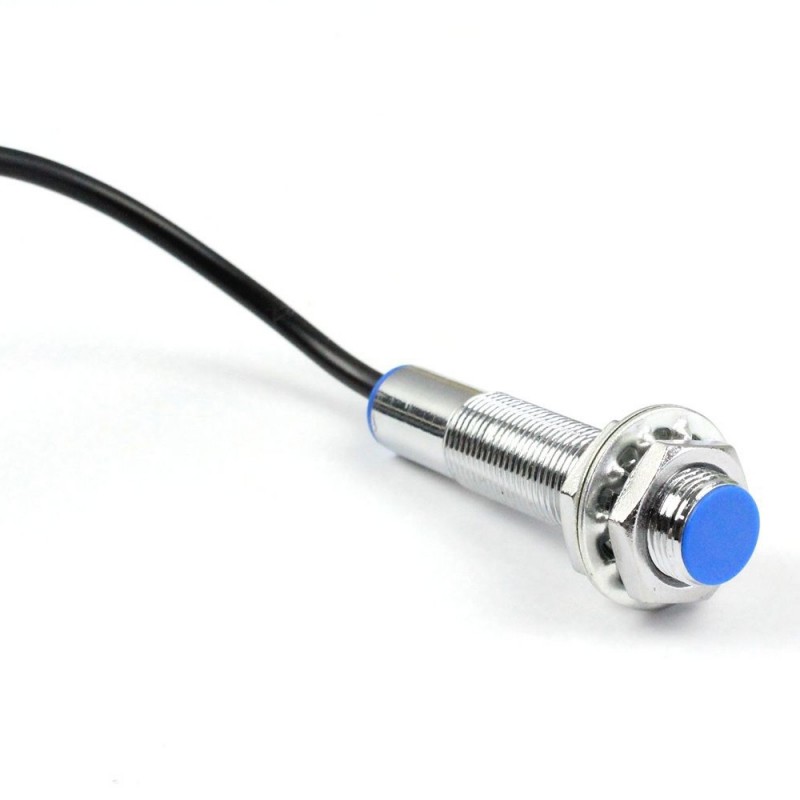
Fallback diagram: qualify the magnet, sensing axis and gap—not only the IC name.

What does a Hall effect sensor actually detect?
It detects a magnetic-field component at its active sensing element, not “an object” in general. A stationary magnet can produce a valid signal. Motion is needed only when the application is measuring movement, rotation or a transition.
Choose the required answer first: magnet present, last magnetic state, or a continuous field measurement. Then check the electrical interface and timing.
Field, not universal metal detection.
A metal target needs a magnetic arrangement that changes the sensed field.
Response and interface are separate.
A digital bus can carry field measurements, not just a binary state.
Polarity is not direction coverage.
Omnipolar means either pole along the relevant sensing axis.
Small packages are not interchangeable.
Match pinout, thresholds, startup, output circuit and complete suffix.
How does the physical effect become a usable signal?
A bias current moves charge carriers through the Hall element. A perpendicular magnetic-field component deflects them sideways, creating a transverse voltage. Reverse that field component and the Hall response reverses. The IC then amplifies and conditions the signal before presenting it to your circuit.
Physics reference: Allegro, Hall-Effect Sensor ICs, AN296065.
Flux density is commonly given in millitesla (mT) or gauss (G): 1 mT = 10 G. A single-axis IC measures one field component. Turning its package can therefore change the result without changing the magnet-to-package distance. Use the manufacturer's sensing-axis and active-area drawings; the marked face is not a universal polarity convention.
Which Hall response type fits your mechanism?
A door that must report open after a magnet moves away needs different behavior from a rotating multipole magnet. The distinction becomes obvious only when you test the return movement, not just the approach.
Swipe the table sideways on a small screen.
| Response | What it does | Question to resolve |
|---|---|---|
| Unipolar switch | Operates for one specified field polarity; releases as that field weakens past its release point. | Is magnet orientation controlled? |
| Omnipolar switch | Can operate for either field polarity along its sensing axis. | Must either magnet pole trigger detection? |
| Bipolar latch | Changes state at one polarity and resets at an opposite-polarity threshold. | Will the motion provide both polarities? |
| Linear / field measurement | Reports a field-dependent value over a specified range. | Do you need field, position or angle information rather than just presence? |
A latch can retain its state while the field returns to zero. That does not mean it remembers the state across loss of power. TI's DRV5013 datasheet, for example, specifies an indeterminate startup output when the field is between its thresholds.
Also separate digital output from digital measurement. An on/off switch might connect to a GPIO. The TMAG5273 instead reports three-axis magnetic measurements over I2C. “Digital Hall sensor” alone is not a complete purchasing specification.
How do BOP, BRP and hysteresis affect the full movement?
BOP is the magnetic operate point; BRP is the release point. Their separation is hysteresis. In a positive-field switch with illustrative thresholds of +5 mT and +3 mT, +4 mT can correspond to either state: it depends on which threshold was crossed previously.
For a bipolar latch with illustrative thresholds of +5 mT and −5 mT, removing a positive field is not enough to reset it. That requires the opposite field. The interactive sequence below makes this distinction visible.
What happens when the same field drives a switch and a latch?
Illustrative models, not specifications for any named part. Both use a non-inverted active-low output with a valid pull-up. Initialization is at 0 mT: the switch is released; the latch state is unknown. In this ideal model, reaching a threshold changes state.
Last applied field: 0 mT
BOP = +5 mT · BRP = +3 mT
At 0 mT, the release condition is satisfied.
BOP = +5 mT · BRP = −5 mT
No threshold has established a state since initialization.
| Field | Switch output | Latch output |
|---|---|---|
| 0 mT (start) | HIGH | Unknown |
Electrical HIGH means released in this model, not “magnet detected.” Real output inversion, startup delays, sampling and threshold tolerances must come from the exact datasheet. Last eight entries are shown.
How is hysteresis different from production tolerance?
Hysteresis describes the operate-to-release separation of a device. Threshold tolerance describes how its limits may vary. Do not treat BOP maximum minus BRP minimum as a measured hysteresis for one IC. TI's transition-detection application brief distinguishes these effects.
For a separate, hypothetical positive-field switch with BOP maximum +6 mT and BRP minimum +1 mT, a present-state minimum of +8 mT and absent-state maximum of +0.5 mT would give field margins of 2 mT and 0.5 mT. Those are arithmetic margins, not a qualified design. Include temperature, magnet variation, assembly offset and external fields; do not reuse these inequalities for a latch or omnipolar response.
How do you convert a linear Hall sensor's field to voltage?
A first-order analog model is:
VOUT ≈ VQ + S × B
VQ is the zero-field output, S is sensitivity and B is the signed field along the sensing axis. Keep units consistent. A sensitivity of 50 mV/mT is 0.050 V/mT.
What does the DRV5055A2 datasheet predict at 5 V and 25°C?
TI lists a typical 2.5 V zero-field output and typical 50 mV/mT sensitivity under these conditions. Using those nominal values:
- B = −10 mT
- 2.0 V
- B = 0 mT
- 2.5 V
- B = +10 mT
- 3.0 V
The +10 mT example is 2.5 + (0.050 × 10) = 3.0 V. These values do not include offset error, sensitivity tolerance, temperature effects, ADC error or output loading. Other supply conditions have different characteristics.
DRV5055 datasheet, Rev. C, electrical characteristics and magnetic response.
A ratiometric sensor's output characteristics track its supply. Using that supply as the ADC reference can reduce sensitivity to shared supply variation, within the specified ratiometry error. It does not remove all offset, noise or temperature error.
Linear with magnetic field does not mean linear with millimeters. Distance conversion needs the magnet geometry and calibration. If the chosen movement path gives the same field at two positions, one field reading cannot distinguish them.
How far can a Hall sensor detect a magnet in your assembly?
The IC specifies a magnetic threshold or range. Your magnet and assembly determine the field at the active element. Magnet material, size, orientation, travel path, gap and nearby steel all matter. The enclosure gap also differs from the distance to the sensing element inside the package.
Start with the intended motion, then use magnetic modeling and representative measurements to establish the complete field curve. TI's Magnet Selection for Linear Position Applications, Rev. B explains the geometry and material trade-offs.
What does the TIDA-01066 test show about switching distance?
TI's door/window reference-design guide reports a head-on test with the magnet's north-south axis normal to the sensor plane. Table 7 gives these measured switching distances:
¼ in diameter × ⅞ in long23 mmReported measured switching distance
¾ in diameter × 1 in long60 mmReported measured switching distance
The design also places a second Hall sensor away from the primary magnet to detect an external tampering magnet. That is a system arrangement, not a capability inferred from one switch alone.
The lesson: a “20 mm Hall IC” description hides the magnet and geometry. These are historical results from TI's setup, not guaranteed production limits, YURUNOX measurements or evidence of security certification.
A stronger magnet can improve operation at the largest gap but prevent release at the open position. A linear sensor can also exceed its useful range. Check both endpoints and the path between them, not just the most favorable approach.
Why can a Hall sensor pass a hand test but miss a moving target?
A slow hand movement keeps the field above the threshold long enough to be detected. A narrow rotating feature may not. Some low-power Hall switches sample periodically instead of monitoring continuously.
The DRV5032FB is an omnipolar, push-pull device with nominal 5 Hz sampling. That can suit a slowly changing lid state, but the 10 ms example could be missed. It is not enough to calculate a target's average event rate.
Compare the shortest time above the required field threshold with worst-case sensor timing, including startup, sampling variation and response delay. Then verify output edges and the host's interrupt or counting logic. A faster interface cannot recover an event the sensing element never sampled.
Which output interface does your Hall sensor need?
Choose magnetic behavior and electrical connection separately. A correctly positioned magnet cannot fix a floating output or an incompatible logic level.
| Interface | Connection | Check before substitution |
|---|---|---|
| Open-drain / open-collector | A pull-up to a permitted logic rail; output sinks current when active. | Sink current, pull-up voltage, resistor value and rise time. |
| Push-pull | Driven HIGH and LOW into a compatible input. | Logic thresholds, loading and output contention. |
| Analog voltage | ADC or analog signal-conditioning input. | Voltage range, ADC reference, offset, noise and loading. |
| Digital measurement bus | Supported bus, such as I2C, with firmware configuration. | Address, registers, axis mapping, conversion time and data format. |
An open-drain output becomes high impedance when released; without a valid pull-up, its voltage is not defined. A smaller pull-up resistance can speed an edge but increases sink current. Select it against the actual load and electrical limits, not a universal resistor value. Littelfuse's technical information explains the sinking-output requirement.
Verify the exact package pinout, including whether a drawing is a top or bottom view. Check local decoupling, supply at the IC, output polarity and the receiver's thresholds. A three-pin Hall IC is not a passive contact, and a continuity test alone cannot establish its function.
Which Hall sensing job are you solving?

Fallback diagram: qualify the complete magnetic path and motion, not an isolated distance.

How do you qualify presence and position sensing?
For a lid or end-of-travel detector, qualify repeatable state boundaries through approach and withdrawal. For continuous displacement, establish the field-to-position curve and check whether it remains unambiguous across travel.
A Hall arrangement can work through a suitable nonmagnetic barrier without an optical opening. That does not make the IC, connector, PCB or finished assembly waterproof.
How do rotation and speed become a countable signal?
If f is the number of counted events per second and N is the number of those same events per mechanical revolution:
Speed (rpm) = 60 × f ÷ N
For an illustrative 100 rising edges per second and two rising edges per revolution, speed is 3,000 rpm. Count both edges while assuming rising edges only, and the result can be wrong by a factor of two. Determine N from the actual pole pattern, response type and software counting method.
This arithmetic does not establish the maximum supported speed. Check magnetic pulse width, sampling, output rise time and host capture. For angle or motor commutation, the required phase information and magnet geometry need their own design; a generic speed pulse is not automatically an absolute angle measurement.
Application reference: Allegro's Hall-Effect Sensors Applications Guide.

Fallback diagram: current path, Hall element and isolation rating must be qualified together.

How does a Hall current sensor measure current?
Purpose-built Hall current sensors can measure DC and AC within their rated range and bandwidth. TI's TMCS1100, for example, combines an internal current conductor with Hall sensing and an isolated signal path.
Hall sensing does not itself guarantee safe isolation. Working voltage, insulation, heating, current capacity and PCB spacing depend on the specific device and assembly. Do not use a generic position IC or an unrated breakout as a qualified high-voltage measurement system.
What must stay the same when you compare Hall sensor parts?
These are documented examples, not interchangeable substitutes. The short names below still need a complete ordering code, package and applicable revision before approval.
| Device example | Documented characteristic | Preserve in the requirement |
|---|---|---|
| DRV5032FB | Omnipolar switch, push-pull output, nominal 5 Hz sampling. | Magnetic response, logic compatibility and minimum event duration. |
| DRV5013 family | Bipolar latch with open-drain output; inverted and non-inverted variants. | Opposite-pole reset, threshold option and startup behavior. |
| DRV5055A2 | Ratiometric linear analog sensor; typical 50 mV/mT at 5 V, 25°C. | Transfer function, useful field range, supply and error budget. |
| TMAG5273 | Three-axis magnetic measurement with an I2C interface. | Firmware, axis mapping, measurement range and conversion settings. |
For sourcing context, review YURUNOX's Texas Instruments component page. Stock availability or package similarity does not establish magnetic or electrical equivalence.
How should you test and troubleshoot a Hall sensor?
Use a current-limited, low-voltage bench setup within the exact device's ratings. Disconnect it from hazardous machinery before a basic functional check. Observe the specified pinout, decoupling and output load.
- Verify the circuit at the sensorMeasure supply and ground at the IC. Confirm the pull-up, ADC connection or bus configuration and valid output levels.
- Establish polarity and sensing axisUse the package drawing, then move the magnet along the intended path. Test both poles when investigating an unknown response.
- Test approach, withdrawal and startupRecord both transitions. Power up at representative field positions, including the region between thresholds.
- Observe the moving waveformCheck narrow pulses and output edges with suitable test equipment. A handheld meter can miss a short event.
- Repeat the relevant extremesCheck gap, alignment, supply, temperature and external magnetic interference before approving the application.
What should you verify when a replacement never resets?
A presence sensor originally releases when one magnet moves away. A replacement with the same number of leads turns on during approach and stays on afterward. A bipolar latch substituted for a switch is one possible explanation.
Confirm the ordering code and specified reset condition. If a controlled opposite-pole test explains the behavior, the purchasing correction is to restore the required response type, then repeat the complete movement and startup sequence. A successful one-way magnet test was not enough to prove equivalence.
| Symptom | Possible explanation | Evidence to collect |
|---|---|---|
| Output never changes | Wrong axis, pole, pinout or insufficient field. | Supply, output circuit and field at the active area. |
| Stays active | Latch response or field above release limit. | Exact reset behavior and full field path. |
| Erratic switching | Floating node, narrow margin or mechanical motion. | Output waveform and field margins. |
| Pulses disappear at speed | Sampling, response delay or slow edges. | Event duration versus the complete timing budget. |
| Analog output reaches a limit | Field or output range exceeded. | Transfer-function limits and ADC input range. |
What should you specify before buying a Hall effect sensor?
Send the approved part number when available. If alternatives are allowed, say which requirements must remain unchanged and which still need engineering confirmation.
- Function and response: presence, displacement, angle, speed or current; switch, latch or field measurement.
- Magnetic system: magnet material and dimensions, polarity, sensing axes, motion path, gap tolerances, BOP/BRP limits or measurement range.
- Electrical interface: supply, output type and polarity, host logic or ADC range, loading and pinout.
- Timing and startup: shortest event, repetition rate, allowed latency and required behavior after power is applied.
- Production and supply: temperature, complete suffix, package, quantity, required date, traceability and change-control requirements.
If you need a finished industrial sensor rather than an IC, also specify cable, connector, enclosure and environmental requirements. For safety-related functions, component operation alone is not a system safety assessment.
Separate sourcing evidence from application qualification. YURUNOX's quality-assurance information can support the supply review; it does not replace validation of the magnetic design.
Share your approved MPN, quantity and required date, plus the magnet arrangement, gap, response type, supply and shortest event duration. Include whether alternative parts may be considered.
YURUNOX is an electronic-component sourcing partner. Final application qualification remains with your engineering team.
Which technical documents support these Hall sensor claims?
Use the exact revision and ordering code when qualifying a part. The documents below support the physics, device examples, test conditions and interface guidance in this page; they do not make unlike Hall sensors interchangeable.
- Allegro: Hall-Effect Sensor ICs, AN296065Hall element, transverse voltage and signal conditioning.
- Allegro: Hall-Effect Sensors Applications GuideField geometry, motion, sensing axes and application arrangements.
- TI: DRV5032 datasheet, Rev. HDevice variants, magnetic response, output type and sampling.
- TI: DRV5013 datasheet, Rev. NLatch thresholds, inversion variants and startup behavior.
- TI: DRV5055 datasheet, Rev. CNominal analog output, sensitivity, ratiometry and limits.
- TI: TMAG5273 datasheet, Rev. CThree-axis magnetic measurements and I2C communication.
- TI: Transition Detection Using Hall-Effect Sensors, SLYA055AOperate/release points, hysteresis and threshold variation.
- TI: Magnet Selection for Linear Position Applications, SLYA059BMagnet selection and mechanical geometry.
- TI: TIDA-01066 design guide, TIDUC692016 reference design; magnet dimensions and measured switching distances.
- TI: TMCS1100 datasheet, Rev. CHall current sensing with implementation-specific isolation and thermal limits.
- Littelfuse: Hall Effect Sensor Technical InformationOutput interfacing and differences from reed sensing.