

What Is a PMIC? Power Management ICs Explained
A PMIC is a power management integrated circuit. It coordinates how power reaches other components and may combine several regulators, power switches, startup sequencing, monitoring or battery functions. Select it against the complete power tree: input range, rail voltages, load current, timing, operating states and the exact startup configuration.
The PMIC manages energy from a battery or supply; it is not the processor that runs the product. The label alone does not guarantee a charger, a particular regulator topology or a production-ready default configuration.
 PMIC mounted on a DDR5 memory module
What does a PMIC do?
A power rail is a supply path at a defined voltage. One input source can feed several rails because a processor core, memory and interfaces may need different supplies. A PMIC combines some of the conversion and control needed to make those rails work together.
Voltage: match every load, not just the input source.
Current: check each output and the whole power budget.
Timing: verify startup, shutdown and partially powered states.
Identity: retain the full ordering code and configuration.
| Condition | Recommendation | Evidence required | Stop boundary |
|---|---|---|---|
| One simple rail | Start by evaluating a single regulator rather than assuming a PMIC is necessary. | Full input range, output tolerance, load profile and enable behavior. | Do not choose a topology until the worst-case input-to-output relationship is known. |
| Several coordinated rails | Shortlist PMICs whose outputs and control scheme fit the complete power tree. | Rail map, sequence, reset dependencies, active/sleep loads and external passives. | Reject the architecture if any required rail, state or timing dependency is unsupported. |
| Different suffix or programmed variant | Hold substitution for an engineering and configuration review. | Complete order codes, pin functions, default NVM, register map and approved image revision. | Do not release the alternate on package fit or family name alone. |
| Board fails after a change | Capture input, enable, rail timing, reset and fault status before replacing parts. | Waveforms under the failing load, exact configuration and documented fault response. | Do not label the PMIC defective while source, load or startup conditions remain unverified. |
This table is a triage aid, not a design approval. The exact datasheet, technical reference manual and board-level measurements control the decision.
A PMIC manages existing energy; it does not create energy. Nor does integration remove every external component. Switching stages commonly need inductors and capacitors, while the board may still need an upstream supply, protection, filtering or an additional regulator.
The term is not a rigid specification. In everyday board design, “PMIC” often means a multi-function or multi-output power chip. The wider power-management IC category also includes single-purpose devices. Read the actual block diagram before deciding what the part replaces.
Which power functions can a PMIC include?
Conversion, switching, sequencing and monitoring answer different questions. A device may combine several of these blocks, but the letters PMIC do not promise a fixed set.
- Voltage converters
- Create regulated rails from the available input. Check topology, voltage range, load capability and required external parts.
- Load switches
- Connect or disconnect a supply path. They normally do not regulate its voltage; on-resistance, inrush and discharge behavior still matter.
- Sequencer and supervisor
- Control when rails start or stop and detect specified conditions. Check thresholds, reset timing and fault response.
- Battery functions
- May include charging, power-path control or measurements used for fuel gauging. Confirm which functions are in hardware and which need host software.
- Control interface
- Allows supported settings or status to be accessed through pins or a serial interface such as I²C. It does not guarantee permanent programmability.
How is a PMIC different from a regulator or battery charger?
A voltage regulator maintains an output voltage. A battery charger controls charging for a supported battery configuration. A PMIC can contain either function, both, or multiple regulators without a charger. A power-management unit, or PMU, is another context-dependent label: it may describe a separate chip or a block inside a larger device.
Charging, battery protection, cell balancing and estimating remaining charge are separate jobs. A charger feature does not establish that every battery-pack requirement is covered. Likewise, thermal shutdown is protection, not a normal operating target or proof of system safety compliance.
How do sequencing and configuration affect PMIC startup?
The PMIC must establish a usable initial power state before the host processor can run its application. A simplified startup path is:
- Accept input power.The input and enable conditions meet the device's startup requirements.
- Apply initial settings.Fixed defaults, hardware selections or stored configuration determine the first rail voltages and behavior.
- Ramp and supervise the rails.Outputs rise according to the required dependencies. Power-good or reset-related signals indicate specified conditions.
- Hand over supported control.Once powered, the host can request operating modes or read status. Shutdown, sleep and faults follow their own documented rules.
What can a final voltage reading miss?
A multimeter reading taken after boot does not show which rail appeared first, how quickly it rose, or whether an interface drove an unpowered device. There is no universal “core first, I/O second” rule. Combine the sequencing requirements of the actual loads, as explained in Microchip's power-sequencing guide.
Which configuration changes survive a power cycle?
I²C is a communication interface, not a guarantee that every setting survives a power cycle. Separate temporary register values from nonvolatile memory (NVM), and distinguish one-time programmable storage from supported rewritable memory.
What happens if a TPS6521905 is not programmed?
TI describes this user-programmable variant as arriving with its power rails OFF by default. Its EEPROM configuration must be established for the application. A board expecting a factory-configured startup could therefore remain off with an unprogrammed device, without the PMIC being defective.
The production question is specific: who programs the settings, which revision is approved, and how is it verified? See TI's user-programmable PMIC workflow.
How do you choose buck, boost, buck-boost or LDO rails?
These terms describe individual conversion functions. Choosing among them starts with the full input-voltage range and the required output, not just a battery's nominal voltage.
| Function | Voltage relationship | Check before selection |
|---|---|---|
| Buck | Steps a DC input down. | Minimum headroom, duty-cycle limits and load capability. |
| Boost | Steps a DC input up. | Input and switch current at the lowest input voltage. |
| Noninverting buck-boost | Regulates a positive output with input above or below it. | Capability and behavior across the crossover region. |
| LDO | Regulates a lower voltage using a pass element. | Dropout, noise, output capacitance and heat. |
Scroll tables sideways on smaller screens. Topology background: Analog Devices' step-up/step-down guide.
For example, a required 3.3 V rail cannot be assumed to remain regulated by a buck-only stage when its input falls to 3.0 V. The architecture may need a buck-boost stage, a different operating range or a different load requirement. “PMIC” does not resolve that mismatch.
A boost converter's switch-current limit is not its available output current. Also, never connect outputs together to add their ratings unless the device explicitly supports current sharing or that connection. For LDOs, low noise and supply-noise rejection are separate specifications; “linear” does not mean noise-free. See Analog Devices' LDO application guide.
How do real PMICs differ in features and applications?
What does TI TPS65219 provide for processor systems?
The TPS65219 integrates three buck converters and four LDOs, with sequencing and control functions. It is a useful example of a multi-rail processor power solution. Those seven outputs still differ in their voltage ranges and current capabilities; they are not seven identical power supplies. See the official TPS65219 product information.
TI's AM62x application note maps configured variants to different supply, memory and core-voltage needs. The design task is to assign each load to a suitable output and validate the complete power network, rather than simply matching the number of rails. The published AM62x power maps illustrate that process.
What does Nordic nPM1300 add for battery-powered systems?
The nPM1300 combines two buck regulators rated up to 200 mA each, two configurable LDO/load-switch outputs, charging and system-management functions. It addresses a different set of needs from a processor-oriented multi-rail device. These are device-specific capabilities, not a recommendation for an unspecified design.
Its fuel-gauge solution also has a software boundary: the PMIC provides measurements, while a host-side algorithm uses a battery model to estimate state of charge. A feature advertised at system level need not execute entirely inside the PMIC. Nordic documents the division in its fuel-gauge overview.
What does the PlayerData Edge Air case actually show?
In an August 25, 2025 customer story, Nordic reports that PlayerData's Edge Air sports tracker uses an nRF52840 SoC and an nPM1300 PMIC. PlayerData's CEO said the company previously used four discrete ICs to perform the same job.
The useful lesson is functional integration: compare the set of power tasks being replaced, not one PMIC against one regulator. The report does not establish that every design will remove four parts or achieve the same battery runtime. Read the original PlayerData customer story. This is manufacturer-published evidence, not an independent comparison or YURUNOX test.
Why does a PMIC get hot, and how can you estimate loss?
Power conversion is not lossless. The heat depends on topology, load and operating conditions, while temperature also depends on the package, PCB and surroundings. A large voltage drop across an LDO can be a major loss even when the current looks modest.
LDO loss ≈ (VIN − VOUT) × IOUT
LDO efficiency ≈ VOUT ÷ VIN
Buck-stage loss = POUT × (1 ÷ efficiency − 1)
For an illustrative 5 V to 1.8 V, 0.4 A rail, output power is 0.72 W. Neglecting ground current, an LDO loses 1.28 W and has 36% efficiency. If a hypothetical buck stage achieves 90% efficiency at that point, its input power is 0.80 W and its total conversion loss is 0.08 W.
Compare LDO loss with an assumed buck efficiency
This arithmetic compares a step-down operating point. It does not select a PMIC, validate dropout or predict junction temperature. Enter a buck efficiency from the relevant operating point, or keep 90% as an explicit assumption.
Example: 5 V to 1.8 V at 0.4 A; assumed buck efficiency 90%.
- Useful output power
- 0.720 W
- Approximate LDO loss
- 1.280 W
- Idealized LDO efficiency
- 36.0%
- Assumed buck-stage loss
- 0.080 W
Estimated buck-stage input power: 0.800 W.
LDO ground current is neglected. Buck efficiency is an input assumption, not a measured result. Switching-stage loss can be split between the IC and external parts; it is not all PMIC junction heating. Values are rounded.
The lesson is not “always use a buck.” A low-current analog rail with modest headroom may have different priorities. Compare conversion loss, noise, space and transient behavior together. Cooling cannot fix a topology that does not meet the voltage requirement.
Which PMIC specifications must you verify before design-in?
Do the input limits and rail currents cover every load state?
Check minimum and maximum input, every output's voltage tolerance, continuous load, peak load and load-step response. A short activity burst can cause a dip that an idle multimeter reading misses. Do not assume all outputs can run at their individual maximum ratings simultaneously under every thermal condition.
For an input-power estimate, add power demands, not currents from unrelated voltage rails. A 1.8 V load and a 3.3 V load cannot be combined into an input-current figure by simple addition. For cascaded stages, include downstream demand and conversion loss at the upstream stage without counting delivered power twice.
Are active, sleep and shutdown currents measured under matching conditions?
A peak-efficiency number says little about a product that sleeps most of the day. Define which rails, monitors and interfaces remain enabled. Include external leakage and wake-up energy. Then compare the datasheet's quiescent and shutdown figures under matching conditions.
TI's load-switch current guide is a useful reminder that these terms depend on the device and measurement state; it is not a universal PMIC current specification.
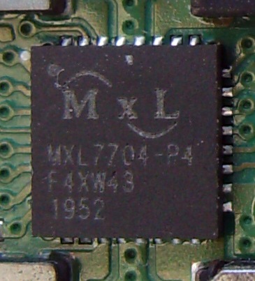 PMIC and neighboring power components on a circuit board
How do passives and layout change PMIC performance?
Inductor saturation, effective capacitance, current-loop routing and heat removal can change performance. A ceramic capacitor's nominal value is not necessarily its effective value under DC bias.
Use the exact device's component limits and layout example. Input capacitors need short, suitable connections; sensitive feedback routes need protection from switching noise. TI's PMIC component-placement guide explains why placing passives is a design task, not a final cosmetic step.
When comparing ripple or transients, record the probe connection, bandwidth and measurement point. A waveform should be evaluated against the relevant limits and test conditions, not just compared visually with a cleaner-looking screenshot.
When should you use a PMIC instead of separate regulators?
A PMIC is attractive when several rails need coordinated behavior and a supported configuration fits the system. Separate devices may suit a rail with unusual voltage, current, noise or physical-placement needs. A hybrid approach is also possible: use a PMIC for the main rails and a separate stage for a special load.
Compare the complete implementation: passives, board area, heat removal, firmware, configuration tools and validation effort. A lower chip price does not prove lower system cost, and greater integration does not automatically mean an easier design.
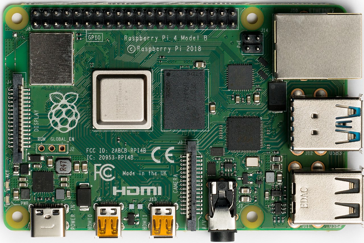 Board-level view of processor, memory, interfaces and power circuitry
How would you map a battery-powered sensor's loads?
Suppose a sensor has an MCU, a radio and an analog measurement section. These requirements are hypothetical, not a reference design for either named PMIC.
| Load | Illustrative need | Question that changes the choice |
|---|---|---|
| MCU and logic | 1.8 V; active and sleep states. | Does the initial rail support boot and the required peak load? |
| Radio | 3.3 V; short transmit bursts. | Does battery voltage cross 3.3 V, and can the rail handle the burst? |
| Analog section | Quiet 1.8 V while measuring. | Is filtering or a separate regulator needed? What happens when it is off? |
First settle the full battery range and load profiles. Next check whether disabling the radio leaves signals driving its unpowered pins. Finally, validate startup, transmit, sleep and wake behavior on the implemented board. If one required rail cannot be supported, revise the power architecture before searching for a package-compatible substitute.
What should a PMIC RFQ and substitute review include?
Why are TPS6521903 and TPS6521904 different startup choices?
TI's TPS65219 datasheet lists an AM62x DDR4 use case at 0.75 V core for TPS6521903 and 0.85 V core for TPS6521904. Those variant identifiers must not be shortened to “TPS65219” when the configuration matters. They are also not complete orderable codes; package and packing information must be retained.
Check the variant's technical reference manual and full ordering information in the TPS65219 datasheet. The comparison illustrates why a suffix can matter; it is not approval to replace one variant with the other.
- Define the electrical requirement.Provide the power tree, input range, rail voltages, load profiles and sequencing dependencies.
- Specify the approved identity.Include the complete ordering code, package, required grade and allowed alternatives.
- Control the configuration.State factory defaults or the approved NVM image/revision, who programs it, and how readback or functional verification is recorded.
- Set the purchasing requirement.Add quantity, delivery target, packaging format and traceability documents needed for the project.
- Approve alternatives through engineering.Compare pin functions, limits, default states, register behavior, passives and board-level results before release.
Keep engineering compatibility separate from evidence about the offered component lot. YURUNOX's purchasing process and quality-assurance information are useful next steps when preparing a sourcing discussion.
How do you troubleshoot a PMIC power-up failure?
A missing rail or failed boot is a symptom, not a diagnosis. Establish the input and enable conditions, capture the relevant startup signals, and preserve fault information before repeated power cycling clears useful evidence.
| Observation | Possible explanation | Check next |
|---|---|---|
| No output at startup | Input or enable condition is invalid; defaults keep rails off. | Input at the IC, enable pins and the exact startup configuration. |
| Rail rises, then collapses | Input droop, excess load or a documented protection response. | Input and output waveforms together, load and fault status. |
| Idle works; activity fails | Load transient or insufficient power margin. | Capture the rail during the actual activity burst. |
| Failure after substitution | Different pin behavior, defaults or configuration. | Full old/new codes, NVM settings and hardware requirements. |
| Unexpected heating | Conversion loss, poor heat removal, excessive load or a fault. | Power budget, temperatures and current under defined conditions. |
Compare observations with the exact device's documented fault response. Some conditions cause retries, others latch an output off. Do not bypass a protection feature to make the board appear to work; find the condition that triggers it.
Make your PMIC requirement clear before sourcing
Send the complete ordering code or BOM, required startup configuration, package and grade. Include quantity, delivery target and approved alternatives so the sourcing discussion starts with the correct component identity.
Which sources support this PMIC guide?
Device examples use published manufacturer documentation. The PlayerData story is attributed to Nordic. Diagrams, the sensor scenario and calculations are illustrative; no YURUNOX circuit tests, customer outcomes or battery-life improvements are claimed.
- Texas Instruments: TPS65219 product information — integrated regulator functions.
- TPS65219 datasheet, Rev. D — electrical limits, configuration variants and ordering information.
- TI SLVAFD0: Powering the AM62x with TPS65219 — example power maps and configured variants.
- TI SSZTCZ8: User-programmable PMIC design — configuration and production workflow.
- Microchip: Why is power sequencing needed? — device-specific startup dependencies.
- Analog Devices: Applying step-up/step-down regulators — input/output relationships.
- Analog Devices: Applying LDOs — dropout, noise and implementation considerations.
- Nordic Semiconductor: nPM1300 and fuel-gauge overview — device capabilities and host-software boundary.
- Nordic: PlayerData Edge Air customer story, August 25, 2025 — attributed integration example.
- TI SLVA757: Quiescent vs shutdown current — load-switch-specific definitions and measurement conditions.
- TI: Placing passive components around a PMIC — board-layout considerations.
Check the latest datasheet and technical reference manual for the exact orderable device before implementation. Photo credits and licenses appear beside each image. For production, self-host optimized WebP copies in the WordPress media library and retain the adjacent attribution; external image URLs are preserved here only as traceable source references. Product names identify examples and do not imply affiliation or endorsement.