

What Is PWM? Duty Cycle and Frequency Explained
PWM, or pulse-width modulation, controls a receiving circuit by changing how long repeated pulses remain active. Duty cycle is the active share of each period; frequency is the number of periods per second. The same percentage can produce different pulse widths, voltage, current, heating or motion, so verify the receiver, polarity, signal levels and load waveform.
Use duty cycle to describe the proportion and frequency to describe the pace. Then follow the signal through the driver to the load before deciding what the PWM command actually does.
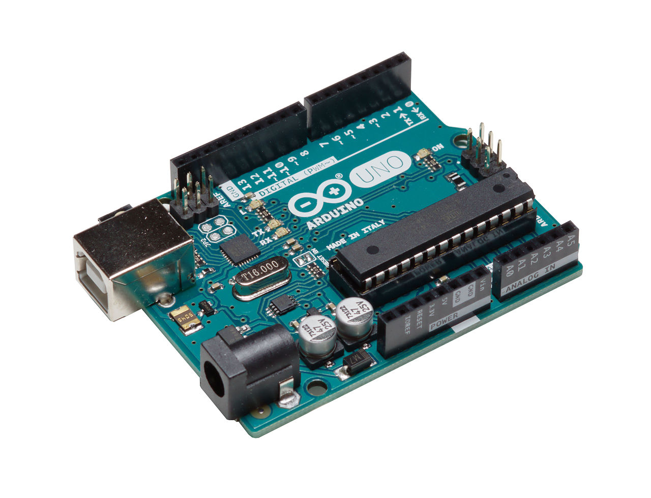
What does PWM actually control?
PWM represents a command through pulse duration. In common fixed-frequency operation, the period stays constant while the active part gets wider or narrower. A receiving circuit turns that timing into a useful result.
50% duty means active for half the cycle. It does not automatically mean half motor speed, half perceived brightness or a smooth voltage equal to half the supply.
Swipe sideways to compare the decision conditions.
| Condition | Interpret PWM as | Evidence required | Stop boundary |
|---|---|---|---|
| Logic command input | Duty, frequency, polarity and voltage levels | Input thresholds, allowed timing range and endpoint behavior from the datasheet | Stop if voltage, reference or polarity compatibility is unknown. |
| Switched resistive load | Pulsed voltage, RMS heating and switch stress | Voltage and current waveforms plus temperature under the intended duty range | Stop if load pulse ratings or thermal limits are not established. |
| Motor or LED driver | A command that the power stage and load reshape | Minimum pulse response, driver output and load-current measurement | Stop if only the logic waveform has been checked. |
| Servo or pulse-encoded interface | Absolute pulse width and allowed update rate | The exact interface specification and device calibration limits | Stop if the requirement states only a duty percentage. |
This guide uses ideal two-level, active-high signals unless stated otherwise. The worked calculations are teaching examples, not recommended settings or measured customer results. Analog Devices’ PWM learning activity provides a useful introduction to the underlying waveform.
How do duty cycle, frequency and pulse width relate?
One period, T, contains a high interval and a low interval. For an active-high input, the high interval is the active pulse. Keep all time quantities in the same unit when calculating duty.
T = tHIGH + tLOW
D = tHIGH / T · Duty (%) = 100 × D
f = 1 / T · tHIGH = D / f
D is a fraction from 0 to 1. Frequency f is measured in hertz, or cycles per second. A 1 kHz signal has a 1 ms period; at 50% duty, it stays high for 0.5 ms and low for 0.5 ms.
Compare ideal 0-to-5 V PWM across a fixed 2 ms window. Change duty to see wider pulses; change frequency to see more or fewer cycles. This is a calculated illustration, not a hardware simulation.
Displayed setting: 50% positive duty at 1 kHz; 0 V LOW and 5 V HIGH.
- Period
- 1,000 µs
- HIGH time
- 500 µs
- LOW time
- 500 µs
- Average voltage
- 2.5 V
The average is calculated from the ideal levels. The raw pin does not become a steady voltage equal to that average.
Swipe the table sideways to compare all timing values.
| Frequency | Duty | Period | HIGH time |
|---|---|---|---|
| 1 kHz | 25% | 1 ms | 0.25 ms |
| 1 kHz | 50% | 1 ms | 0.50 ms |
| 1 kHz | 75% | 1 ms | 0.75 ms |
| 2 kHz | 50% | 0.5 ms | 0.25 ms |
How to use the table: compare the two 50% rows. The fraction is unchanged, but doubling frequency halves the pulse width. That matters when a receiver cannot reproduce very short pulses.
How do polarity and 0% or 100% endpoints change the reading?
For an active-low input, the LOW interval may be the commanded active time. A scope’s positive-duty reading can therefore be the complement of the device’s control duty.
Ideal 0% is continuously LOW; ideal 100% is continuously HIGH. Neither has repeating visible edges, so a frequency counter may report no valid frequency even if the timer is running. Real peripherals can use special endpoint settings, and some power stages require minimum off time. Verify continuous-on support instead of assuming it.
What does the PWM signal control after it leaves the source?
A microcontroller commonly generates PWM with a timer and compare value. Analog PWM can instead compare a control voltage with a repeating ramp. In either case, the resulting signal is a command; the receiving circuit decides what happens next.
- CONTROLLERSets the pulse timingThe output pin supplies a logic-level waveform within its electrical limits.
- RECEIVER / DRIVERInterprets or amplifies itA compatible input, gate driver or power stage handles the next step.
- LOADProduces the useful resultCurrent, light, movement or heat depends on the complete circuit.
A motor winding and its recirculation paths shape current. A filter smooths voltage. A heater responds through thermal inertia. A dedicated fan-control input can decode duty without having its supply voltage chopped.
Switching can be efficient because a transistor spends much of its time conducting with a small voltage drop or blocking with little current. Conduction, transitions and gate drive still cause losses. PWM is a control method, not a promise of lossless operation.
Does 50% PWM mean half voltage or half power?
It means half the cycle is active. What that implies for voltage or power depends on where you measure and what the load is.
When is average voltage the useful PWM quantity?
For fixed high and low levels, the time-average voltage is:
VAVG = D × VH + (1 − D) × VL
A 0-to-5 V waveform at 40% duty averages 2 V. It still switches between 0 V and 5 V. To obtain an approximate analog level, a low-pass filter must suppress the carrier.
The Analog Devices ADALM1000 activity demonstrates reconstruction with an RC filter. Stronger smoothing trades lower ripple for slower response; loading can also shift the result. Check ripple, settling, output impedance and startup behavior. Use buffering or a dedicated DAC when the application requires it.
When does RMS voltage determine PWM heating?
For ideal unfiltered PWM switching directly between 0 V and V across a constant resistance R:
VRMS = V × √D
PAVG = D × V2 / R
Root-mean-square (RMS) voltage describes the equivalent DC heating effect in that resistor. The expression comes from averaging the squared voltage, not squaring the average voltage.
Why do 12 V pulses at 50% duty heat differently from 6 V DC?
Assume a 12 Ω resistor and negligible switching losses. The two signals below both average 6 V, but they do not produce the same heat.
Swipe sideways to compare PWM with steady DC.
| Quantity | 0-to-12 V PWM, 50% | Steady 6 V DC |
|---|---|---|
| Average voltage | 6 V | 6 V |
| RMS voltage | About 8.49 V | 6 V |
| Average power | 6 W | 3 W |
| Load current | 1 A while ON; 0 A while OFF | 0.5 A continuously |
The consequence: using 62/12 for the PWM case would understate heating by half. The resistor receives 12 W during each ON interval, then zero during OFF, giving a 6 W average.
This calculation is not a heater design recommendation. Resistance changes with temperature, pulse ratings and thermal conditions matter, and inductive motors, current-regulated LEDs and filtered converter outputs require different waveform analysis.
How do you choose a usable PWM frequency?
Start with the receiving device’s allowed range. Then check the load response, minimum pulse times, switching losses, acoustic behavior and electromagnetic interference (EMI). There is no best number for every PWM application.
What changes when PWM frequency increases?
It can reduce some current ripple or ease filtering, but more transitions per second can increase switching-loss power. A fixed delay or dead time also occupies a larger fraction of a shorter cycle.
TI’s motor-control guidance describes the balance between current harmonics, acoustic noise, switching losses and dead-time distortion. Moving a carrier out of an audible range does not guarantee a silent mechanism.
Dead time is a non-overlap interval between complementary power switches, used where required to prevent simultaneous conduction. Do not remove it just to regain duty range. Follow the driver’s timing requirements and verify the effective waveform.
What happens when a driver requires a 2 µs minimum pulse?
Assume the driver needs at least 2 µs of active time to produce a usable pulse. That represents only 0.2% of a 1 kHz cycle, but 4% of a 20 kHz cycle.
DMIN ≈ tMIN × f
The 2 µs value is an assumption, not an industry-wide specification. The lesson is to check usable pulse duration—not just maximum PWM frequency. Minimum inactive time and startup delay can impose further limits.
What changes when PWM frequency decreases?
Longer periods give a slower driver more time and, at the same timer tick rate, provide more timing increments per cycle. But they can bring greater ripple, visible artifacts or audible effects. Test the lowest intended command, startup and changing load; a plausible multimeter reading alone does not establish good operation.
How do LEDs, motors, servos and converters interpret PWM differently?
How should LED PWM dimming be validated?
In a suitable constant-current LED driver, PWM dimming turns regulated current on and off. Average current can approximately track duty if each pulse reaches the intended current and transition effects are small. Perceived brightness and camera appearance need separate checks.
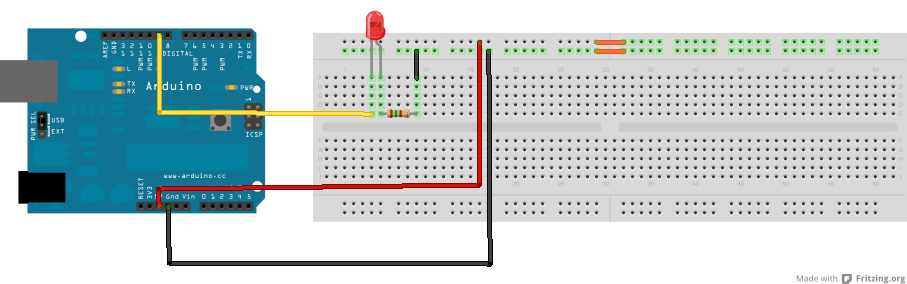
At low duty, turn-on delay and current settling can consume much of the pulse. Check actual LED current, optical artifacts and camera banding in the intended use. A universal “flicker-free” frequency would ignore the driver, waveform and observer or camera conditions.
How can 240 Hz dimming coexist with a 390 kHz oscillator?
TI’s TIDA-01183 automotive-lighting reference design lists a PWM dimming condition at 240 Hz and a separate typical 390 kHz oscillator frequency for the TPS92691-Q1 LED driver.
These numbers describe different functions: the dimming command and the converter’s internal switching. Neither is a universal LED setting. When comparing parts, identify which frequency a datasheet or quotation actually describes.
Source: TIDUC97A, revised January 2017, Table 1 on page 3. This is a published design example, not a YURUNOX test.
Why does 50% duty not guarantee 50% motor or fan speed?
Motor current depends on the winding, supply and drive circuit. Speed also depends on load, friction, back electromotive force and feedback. If speed must remain stable under changing load, evaluate closed-loop control.
Check what OFF means: a driver may brake, coast or recirculate current differently. For a fan with a dedicated PWM input, follow that interface specification. Chopping supply power is not automatically equivalent to using the control input.
Why must a hobby servo be specified by pulse width?

Pololu’s detailed servo-interface explanation identifies pulse duration as the central command quantity. About 1.5 ms is a common neutral reference, but exact limits and calibration vary.
Illustrative comparison: 1.5 ms repeated every 20 ms is 7.5% duty. Keep 7.5% duty but shorten the period to 10 ms, and the pulse becomes 0.75 ms—a different command, potentially outside the allowed range.
For a servo, specify pulse duration and permitted update rate, not a duty percentage alone. Do not assume a particular pulse always means the same angle across different servo models.
What must be checked for converters and heaters?
A switching converter’s output depends on its topology, operating mode and feedback loop. Do not apply one converter’s duty relationship to every design. Thermal loads may tolerate slower switching, but the switch technology still matters: a mechanical relay is not a substitute for a transistor switching at kilohertz rates.
How does PWM frequency limit timer resolution?
A timer can place edges only at available clock instants. For a simple edge-aligned counter with an effective tick rate fTICK and N timing intervals per cycle:
fPWM = fTICK / N
Duty increment ≈ 1 / N
N is a count of intervals, not a universal register value. Prescalers, counting modes and endpoint behavior vary. Microchip AN539 explains the frequency-resolution trade-off for its example device; use your controller’s manual for implementation.
What does a 48 MHz timer provide at 20 kHz and 200 kHz?
Assume a 48 MHz effective tick rate with no further division. At 20 kHz, there are 2,400 intervals per cycle, giving an increment of about 0.0417 percentage points. At 200 kHz, only 240 intervals remain, so the increment is about 0.4167 percentage points.
That is ten times coarser duty control. It does not mean ten times worse overall accuracy: clock tolerance, jitter, driver delay and load behavior are separate limitations.
Also check shared timer resources, synchronized updates, complementary outputs and fault handling. Edge-aligned and center-aligned modes place edges differently and can require different frequency formulas. Microchip’s PWM peripheral overview illustrates why a nominal bit-depth label is only part of the selection.
How should you measure and troubleshoot a PWM signal?
An oscilloscope separates pulse width, period, amplitude and edge behavior. A meter’s DC reading may resemble the average, but it cannot by itself show missed pulses, ringing or a receiver that never recognizes HIGH.

Start at the receiving pin. Confirm high and low levels, period and active pulse duration. Then compare the observed duty with the command, accounting for polarity.
Check the driver output and load current next. A correct-looking logic input cannot prove that short pulses survive propagation delay or that the load receives the intended current.
Measurement safety: never defeat an oscilloscope’s protective earth to probe a floating switch node. Use an appropriately rated differential or isolated measurement system within its voltage, common-mode, category and bandwidth limits. High-voltage and motor-drive measurements require suitable training and procedures. See Tektronix’s probe primer.
Swipe the troubleshooting table sideways for the next check.
| Symptom | Possible explanation to check | Next step |
|---|---|---|
| Duty changes; output does not | Enable state, polarity, current limit or suppressed short pulses | Measure the driver output and read fault/status signals. |
| Frequency changes unexpectedly | A shared timer or changed clock configuration | Review every channel using that time base. |
| More heat at higher frequency | Switching losses, gate-drive limitations or changed load current | Compare current, transitions and temperature at the same load. |
| Unstable low-duty response | Minimum pulse time, startup threshold or limited resolution | Verify the minimum usable command under load. |
Use symptoms as starting points, not diagnoses. Record supply voltage, load, frequency, duty, temperature and measurement location. Include startup, shutdown and duty endpoints. A no-load waveform may not explain a failure during motor startup.
What must engineers and buyers specify before ordering a PWM-capable part?
For a controller, driver, fan or LED module, “supports PWM” is only the beginning. Put the following requirements beside the full manufacturer part number when reviewing a quotation or alternative.
- Which kind of PWM interface?A logic command, a switched power output and a pulse-width servo interface are not equivalent.
- Which electrical levels and polarity?Confirm HIGH/LOW thresholds, input tolerance, reference connection and input structure.
- Which usable timing range?Specify frequency, minimum active and inactive times, required duty range, and 0%/100% behavior.
- Which load and power limits?State the supply, current, voltage, thermal conditions and required current recirculation or protection.
- Which resolution and update behavior?Check effective duty steps at the chosen frequency, shared timers and synchronized changes.
- Which startup and fault response?Agree on enable behavior, overcurrent protection, shutdown and the safe state if the command disappears.
A higher maximum frequency or larger advertised resolution does not establish compatibility. Obtain engineering approval before treating an alternative as a drop-in replacement. YURUNOX’s purchasing process and quality-assurance information help frame the separate sourcing and documentation requirements.
Send the full part number or required function, quantity, load, supply voltage, signal levels, frequency and duty range. Include minimum pulse requirements and the protection behavior your design needs.
YURUNOX is an electronic-component sourcing partner. Clear electrical requirements help keep the sourcing review aligned with engineering approval.
Which technical documents support these PWM calculations and examples?
Published design values apply to the cited conditions. Waveforms and numerical teaching examples are calculated illustrations, not field measurements or customer case histories.
- Analog Devices — ADALM2000 Activity: Pulse Width ModulationDuty, frequency and PWM generation principles.
- Analog Devices — ADALM1000 PWM activityFiltering, reconstruction and residual carrier.
- Texas Instruments — Selection of PWM FrequencyTI expert guidance on motor-control trade-offs, not a universal setting.
- Texas Instruments — TIDA-01183 design guide, TIDUC97A240 Hz dimming condition and separate typical 390 kHz LED-driver oscillator; Table 1, page 3.
- Pololu — Servo control interface in detailPulse-width command semantics and device-dependent calibration.
- Microchip — AN539: Frequency and Resolution Options for PWM Outputs and PWM peripheral overviewTiming resolution, alignment modes and peripheral selection.
- Tektronix — ABCs of Probes PrimerProbe selection and floating-measurement safety.
External image sources, authors and licenses are listed beside each figure. Images illustrate circuits and devices; they are not presented as YURUNOX inventory or testing evidence.